


CHAPTER 3 EXPOSURE SYSTEM
COPYRIGHT
©
1999 CANON INC. CANON PC800s/900s REV.0 AUG. 1999 PRINTED IN JAPAN (IMPRIME AU JAPON)
3-9
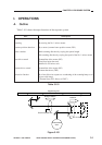
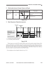
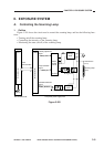
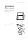
Figure 3-201
(Q101)
Serial
communication
VR107
DC controller PCB
Microprocessor
(Q900)
Intensity adjustment
signal
PWM_1KHz
Lamp activation
signal
LAMP_ON
Activation detection
signal
LAMP_DETECT
Composite power supply PCB
9
4
2
7
(HIC001)
Phase
control
circuit
Arcing circuit
Scanning lamp
(LA1)
Thermal fuse
(FU1)
Activation detection circuit
Rectifying
circuit
Microprocessor
Rectifying
circuit
+
-
+
-
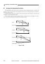
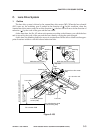
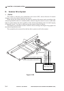
II. EXPOSURE SYSTEM
A. Controlling the Scanning Lamp
1. Outline
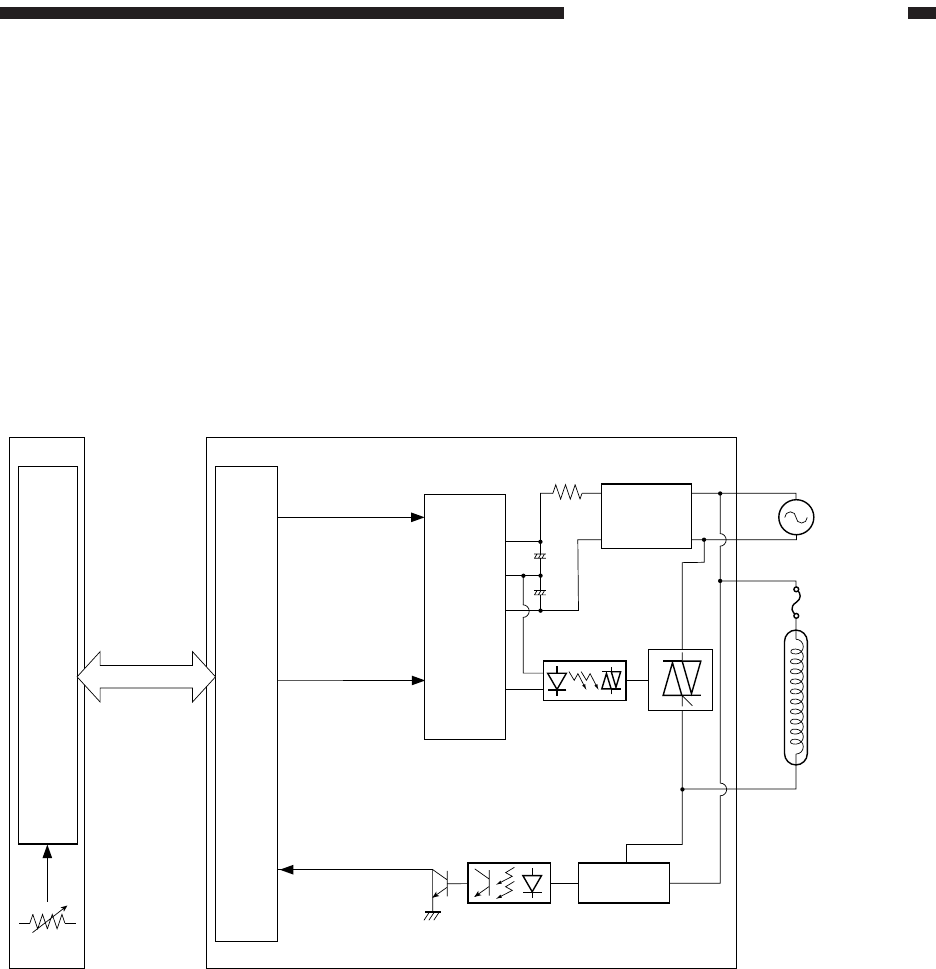
Figure 3-201 shows the circuit used to control the scanning lamp, and has the following func-
tions:
• Turning on/off the scanning lamp.
• Controlling the intensity of the scanning lamp.
• Monitoring the state (on/off) of the scanning lamp.