


CHAPTER 5 PICK-UP/FEEDING SYSTEM
COPYRIGHT
©
1999 CANON INC. CANON PC800s/900s REV.0 AUG. 1999 PRINTED IN JAPAN (IMPRIME AU JAPON)
5-6
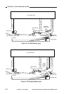
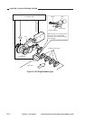
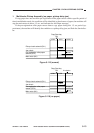
Figure 5-106
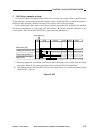
M1
SL1
SL4
Cam gear
Spring clutch
Control ring
Lifter
Multifeeder pickup roller
Paper guide
plate
Copy paper
DC controller PCB
Multifeeder pickup
solenoid drive
signal (MFSLD*)
Pickup clutch
solenoid drive
signal (PUSLD*)
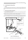
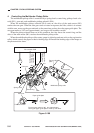
Cam gear
Paper guide plate
The cam gear makes a 180˚ turn (approximate),
causing the paper guide plate to move up and down.
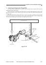
Claw
Toothless section
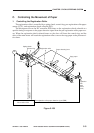
4. Controlling the Multifeeder Pickup Roller
The multifeeder pickup roller is controlled by a spring clutch, control ring, pickup clutch sole-
noid (SL1), gear unit, and multifeeder pickup solenoid (SL4).
When the multifeeder pickup solenoid (SL4) turns on, the drive of the main motor (M1)
reaches the cam gear. When the cam gear starts to rotate in response, the lifter, which is in contact
with the cam, moves up the gear unit and, at the same time, pushes down the paper guide plate. The
cam gear makes a 180° turn (approximate), and stops at the toothless section.
When the pickup solenoid turns on in this condition, the claw leaves the control ring, and the
drive of the main motor (M1) reaches the multifeeder pickup roller.
When the multifeeder pickup roller rotates, paper is picked up and sent as far as the registration
roller, which controls the paper so that its leading edge will match the leading edge of the image on
the photosensitive drum.