


CHAPTER 11 TROUBLESHOOTING
COPYRIGHT
©
1999 CANON INC. CANON PC800s/900s REV.0 AUG. 1999 PRINTED IN JAPAN (IMPRIME AU JAPON)
11-71
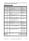
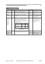
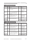
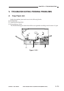
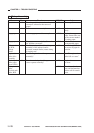
19 The scanner fails to move forward.
YES/NO
NO
NO
NO
NO
YES
NO
Cause
Cable
Scanner path
Composite
power
supply PCB
Pre-registra-
tion roller
paper sensor
(Q751)
Scanner/lens
drive motor
(M2)
DC controller
PCB
Step
1
2
3
4
5
Checks
Is the scanner drive cable routed
correctly?
Is the scanner rail soiled?
Move the scanner by hand. Does it
move smoothly?
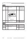
Set the meter range to 30 VDC, and
connect the meter probes to J202-2 (+)
and -1 (-) on the composite power
supply PCB. Is the meter reading
about 24 V?
Is the pre-registration roller paper
sensor (Q751) normal? (For instruc-
tions on how to check the
photointerrupers, see p. 11-47.)
Replace the scanner/lens drive motor
(M2). Is the problem corrected?
Action
Route the cable
correctly.
Check the surface of
the scanner rail for
dirt, foreign matter, or
object which may
interfere.
See “DC power fails
to turn on.”
Check the wiring from
J108 on the DC
controller PCB to
Q751; if normal,
replace Q751.
End.
Replace the DC
controller PCB.
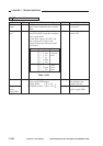
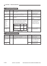
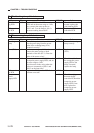
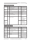
20 The registration roller fails to rotate.
Yes/No
No
No
No
Yes
No
Cause
Main motor
(M1)
Pre-registra-
tion roller
paper sensor
(Q751)
Registration
roller spring
clutch
Registration
clutch
solenoid
(SL2)
DC control-
ler PCB
Step
1
2
3
4
Checks
Does the main motor (M1) start to
rotate when the Copy Start key is
pressed?
Is the pre-registration roller paper
sensor (Q751) normal? (For instruc-
tions on how to check the
photointerrupers, see p. 11-47.)
Does the registration clutch solenoid
(SL2) turn on for a moment after the
Copy Start key is pressed?
Set the meter range to 30 VDC. Does
the voltage between J109-6 (+) and -5
(-) on the DC controller PCB change
to about 24 V for a moment after the
Copy Start key is pressed?
Action
See “The main motor
fails to rotate.”
Check the wiring from
J108 on the DC
controller PCB to
Q751; if normal,
replace Q751.
Check the position of
the solenoid; if nor-
mal, check or replace
the control ring.
Check the wiring from
J109 on the DC
controller PCB to SL2;
if normal, replace SL2.
Replace the DC
controller PCB.