


CHAPTER 4 IMAGE FORMATION SYSTEM
COPYRIGHT
©
1999 CANON INC. CANON PC800s/900s REV.0 AUG. 1999 PRINTED IN JAPAN (IMPRIME AU JAPON)
4-9
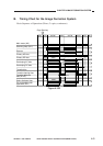
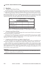
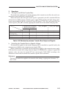
T_REV_ON* signal
1
0
1
1
Negative transfer bias ON
Positive transfer bias ON
(cleaning bias)
Transfer bias OFF
ATVC
Transfer bias ON signal
(serial communication)
bit2 bit3
10
11
00
01
T-FW_ON signal
1
1
0
1
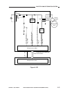
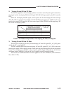
2. Operations
a. Turning On and Off the Transfer Bias
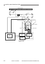
The transfer bias applied to the transfer charging roller is turned on and off by the serial com-
munication signal from the DC controller PCB.
When the transfer bias ON signal (serial signal) is generated by the DC controller PCB, the
microprocessor (Q900) on the composite power supply PCB generates the high-voltage trans-
former control signal (CLK32K), transfer DC bias ON signal (T_FW_ON), and transfer DC bias
control signal (T_FW_DRV), thereby applying the transfer bias to the transfer charging roller.
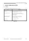
Table 4-103 Relationship between Transfer Bias Output and Signals
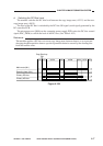
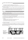
b. Controlling the Transfer Bias to a Specific Voltage
The transfer bias applied to the transfer charging roller is controlled to a specific level by the
microprocessor (Q900) on the composite power supply PCB.
When a transfer bias is generated, the microprocessor (Q900) on the composite power supply
PCB checks the transfer bias voltage detection signal (T_FEEDBACK), compares it against the
reference value, and varies the transfer DC bias control signal (T_FW_DRV) according to the
difference to ensure that the transfer bias remains a specific level at all times.
Reference:
The level of transfer bias applied to the transfer roller during a copying run is between -7.5
and -3.0 kV.