


CHAPTER 4 IMAGE FORMATION SYSTEM
COPYRIGHT
©
1999 CANON INC. CANON PC800s/900s REV.0 AUG. 1999 PRINTED IN JAPAN (IMPRIME AU JAPON)
4-13
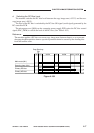
DC bias ON
DC bias ON
(- 500V)
DC bias OFF
Developing DCON signal
(Serial communication)
bit5 bit6
–1
01
00
DV_DC_ON
(J103-3)
0
1
1
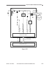
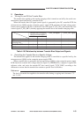
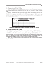
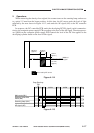
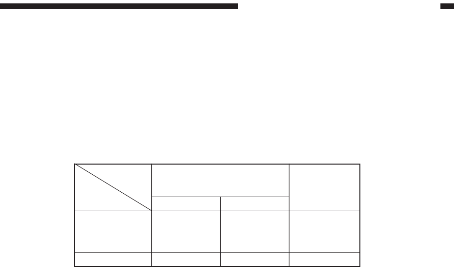
2. Turning On and Off the DC Bias
The DC bias applied to the developing cylinder is turned on and off by the signal communica-
tion signal and the developing DC bias ON signal (DV_DC_ON) generated by the DC controller
PCB.
When the developing DCON signal (serial signal) and the developing DC bias ON sign
(DV_DC_ON) are generated by the DC controller PCB, the microprocessor (Q900) on the com-
posite power supply PCB sends the DC bias control signal (BIAS_PWM), thereby applying a DC
bias to the developing cylinder.
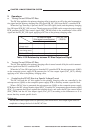
Table 4-104 Relationship between Developing DC Bias and Signals
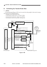
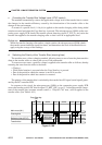
3. Turning On and Off the AC Bias
The AC bias is turned on and off by the developing AC bias ON signal (DV_AC_ON) gener-
ated by the DC controller PCB.
The DC controller PCB sends the developing AC bias ON signal (DV_AC_ON) to the com-
posite power supply PCB a specific period of time after copy paper has moved past the registration
sensor. The microprocessor (Q900) on the composite power supply PCB generates the AC bias
oscillation signal (ACBIAS) so that an AC bias is applied to the developing cylinder.
The AC bias is modified/rectified and then supplied to the static eliminator (static eliminator
bias, about 3.2 kV).