


2-22
Step 4 Install the Camera
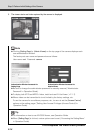
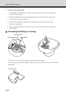
5. Connect the LAN cable, and also connect each external device using a cable.
Connect the LAN cable that has been guided through the wiring hole, to the LAN cable on the
camera side.
If necessary, connect the audio, I/O or power interface cable to each external device.
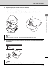
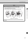
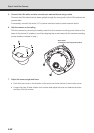
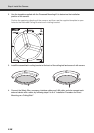
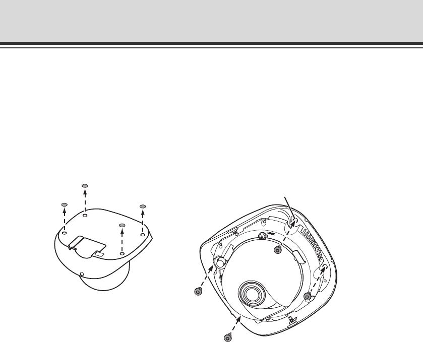
6. Affix the camera on the ceiling.
Affix the camera by removing the safety sheet from the camera mounting screw holes on the
base of the device (4 locations), and then aligning the screw holes with the camera mounting
screw locations marked in step 1.
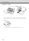
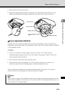
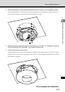
7. Adjust the camera angle and focus.
• Push the inner cover in the direction of the arrow, as shown below, to remove the cover.
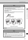
• Loosen the pan, tilt and rotation lock screws and adjust the lens in a desired direction,
and then lock the screws.
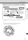
Screw holes
(4 locations, Φ4.6 mm(Φ0.18 in), M4.0)