


3-6
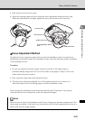
Input/Output Terminals
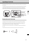
External Device Input Terminals (IN1, IN2)
There are two sets of external device input terminals (IN1, IN2), where each set consists of two
terminals. The - terminals are connected to the GND in the camera. Two-wire cables are
connected to the + and - terminals to achieve electrical continuity or insulation between the two
terminals for notification to the viewer.
External Device Output Terminals (OUT1, OUT2)
There are two sets of external device output terminals (OUT1, OUT2), where each set consists of
two terminals. Each terminal set has no polarity. The condition between the two terminals can be
switched between connected and disconnected by controlling from the viewer. The output
terminals are isolated from the internal circuits of the camera using optical couplers.
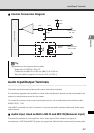
The loads connected to the output terminals should be used within the following ratings:
Ratings between output terminals: Maximum voltage 50 VDC
Continuous load current 100 mA max.
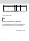
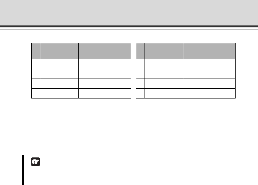
Color of spare
wire
Type of corresponding
terminal
Color of spare
wire
Type of corresponding
terminal
1 Black OUT2_B 5 Yellow IN2_-
2 Brown OUT2_A 6 Green IN2_+
3 Red OUT1_B 7 Blue IN1_-
4 Orange OUT1_A 8 White IN1_+
Note
For the sensors and switches to be connected, connect terminals that are electrically isolated
from each power supply or GND.