


User’s Manual
9
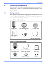
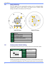
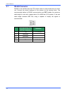
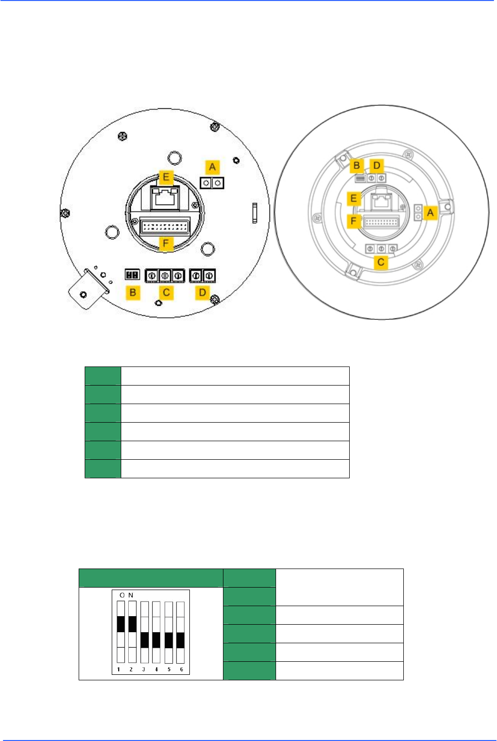
2.2 Switch Definition
The PTZ camera ID and communication protocol must be configured before
connecting the camera to other devices. The switches used to configure these
settings are located on the bottom of the PTZ camera.
Indoor PTZ camera Outdoor PTZ camera
A
Reserved
B
Communication switch
C
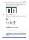
PTZ camera ID switch
D
PTZ Camera Control Protocol
E
RJ-45 connector (for IP camera only)
F
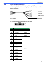
22-pin connector
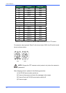
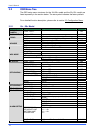
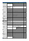
2.3 Communication Switch Setting
The table below shows the function of each pin within the communication switch.
Communication switch Pin 1
Pin 2
RS-485 setting
Pin 3
Termination
Pin 4
Line lock
Pin 5
System initialise
Pin 6
Reserved
RS-485 is the interface that allows the PTZ camera to communicate with its control
unit; the RS-485 configuration on the PTZ camera and the control unit must therefore