


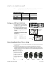
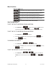

3-PIN TO 5-PIN CONVERSION CHART
th a 5 pin DMX output connector, you will need to use a 5
pin to 3 pin adapter. CHAUVET Model No: DMX5M, or DMX5F.
3
PIN TO 5 PIN C
duc 3 Pin Female (output) 5 Pin Male (Input)
Note! If you use a controller wi
The chart below details a proper cable conversion:
ONVERSION CHART
Con tor
Ground/Shield Pin 1 Pin 1
Data ( - ) signal Pin 2 Pin 2
Data ( + ) signal Pin 3 Pin 3
Do not use Do not use
Do not use Do not use
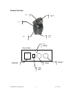
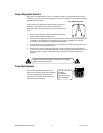
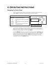
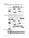
This drawing provides a
general illustration of the
DMX Input/Output panel of
a lighting fixture.
U X Controller niversal DM
Continue the link
O
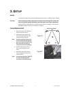
and Standalone operation requires
that the first fixture in the chain be
initialized for this purpose via either
settings in the control panel or DIP-
switches. Secondarily, the fixtures
that follow may also require a slave
setting. Please consult the
“Operating Instructions” section in
this manual for complete instructions
for this type of setup and
configuration.
ften, the setup for Master-Slave
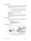
Setting up a DMX Serial Data Link
e of
pin
2.
a (female) 3
3. t
ove to the input of the following
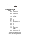
escription
.5m/14.8ft
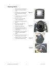
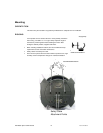
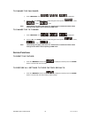
Stand-Alone/Master/Slave Fixture Linking
X cable to the output (female) 3 pin connector
of the first fixture.
f the next fixture consisting of a (male) 3 pin connector. Then,
so on.
1. Connect the (male) 3 pin connector sid
the DMX cable to
the output (female) 3
connector of the controller.
Connect the end
of the cable coming from
the controller which will have
pin connector to the input connector of the
next fixt
ure consisting of a (male) 3 pin
connector.
Then, proceed to connect from the outpu
as stated ab
fixture and so on.
CH
AUVET Certified DMX Data Cables
Order Code D
DMX1.5 DMX Cable 1.5m/4.9ft
DMX4.5
DMX Cable 4
DMX10 DMX Cable 10m/32.8ft
1. Connect the (male) 3 pin connector side of the DM
2. Connect the end of the cable coming from the first f
ixture which will have a (female) 3 pin
connector to the input connector o
proceed to connect from the output as stated above to the input of the following fixture and
Intimidator Spot 2.0 HTI Manual 11 2007-01-24/09:36