


16
Chapter 3: Wiring and Setup
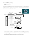
3.1 Basic Configuration
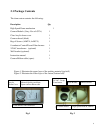
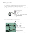
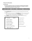
The illustration below provides the basic electrical wiring configuration for connecting and testing a single dome to a
test monitor and a joystick / keyboard controller. When installing the product for the first times please read the
installation instructions carefully and become familiar with the electrical connections and setup options. Incorrect
wiring may result to permanent damage of the equipment.
In the above illustration, JMP-120R is the impedance matching selection of control signal and noise restrain of
RS-485. When the dome control is done over long cable run or there is a need for noise limiting, you need to install
this jumper (provided) together with the set of screws. For normal runs up to 500 feet no action is required.
Caution: This operation should be performed with the power removed (Power OFF).
/ Grounf
GND Wire / Not needed
during testing phase
Wiring Harness
Video
GND/Not needed during testing phase
8 Pin Header
Connector
Video
GRND
AC24V (
Red
)
AC24V (Black)
RS485
signal+ (orange)
RS485
signal
-
(yellow)
Test
Monitor
Joystick /Keyboard
Controller
24VAC
Transformer
12 VDC
Transformer