


Power Spot 700 II™
©Elation Professionals® Los Angeles, Ca. - wwww.ElationLighting.com - Page 13
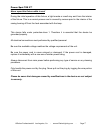
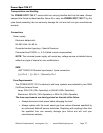
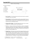
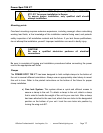
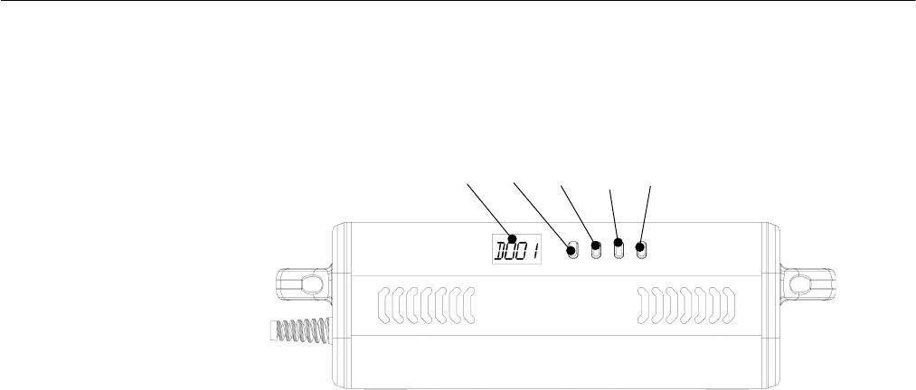
20.4-Segment LED Menu
Display
21. Mode Button
22. Enter Button
23. Up Button
24. Down Button
Side View - Menu and Display
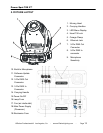
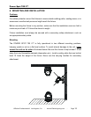
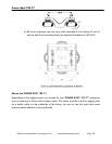
1. Head Assembly – The head assembly consist of the main output lens, and either
the standard or CMY control module.
2. Carrying Handle – The fixtures includes two built-in carrying handles. Be sure to
always handle the fixture by the built-in carrying handles. Never lift or carry the
fixture by the head or retaining arms as this could cause serious damage to the
fixture and void your manufactures warranty.
3. 4-Segment Menu Display – This display details all the various menu functions.
See page 23 for a detailed breakdown of the operating menu.
4. Tilt Lock – This lock will hold the head assembly in place for transportation
and/or service. Depress the lock button to lock and unlock the head assembly.
The head will lock in a 90˚ or 45˚ orientation. Always be sure to unlock the head
assembly before applying main power to the unit. Failure to do so will result in a
start-up error and may damage the unit.
5. Omega Clamp - This fixture uses a cam-lock clamp system that allows a quick
and efficient means to secure a clamp to the unit. To attach a clamp to the unit,
attach a clamp that is rated to handle the weight of the unit to your omega clamp.
After a clamp has been attached to the omega clamp, attach the cam locks to the
designated position on the bottom of your unit. Lock the cam locks into position by
turning the wing nuts 90°. See page 17 for proper clamp mounting and assembly.
6. Ethernet Jack – This jack is used for arcnet DMX protocol.
20
21
22
23
24