


4-36
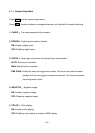
RELAY
JP6
JP4
JP3 JP1
JP5
Video +
Video -
RS485 +
RS485 -
AC24
AC24
JP5
1 ~ 9
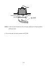
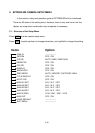
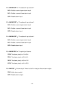
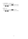
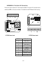
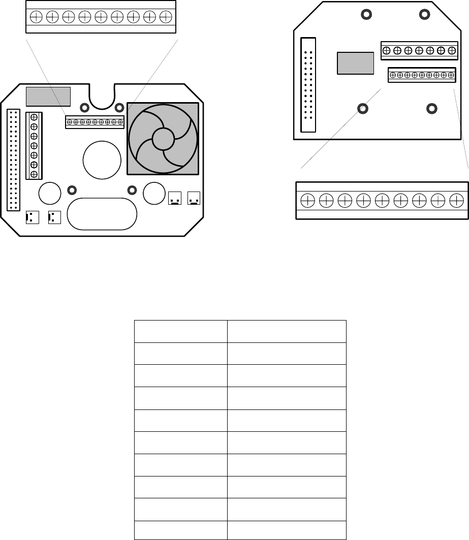
APPENDIX A: The Alarm I/O Connection
There are 4 alarm inputs and 1 alarm output available. The alarm I/O connector that is
marked as JP5 is a nine-pin connector. It is located on the PCB board of the housing.
EPTZ900 base board EPTZ500 base board
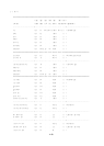
Pin # Function
1 Alarm Input 4
2 Ground
3 Alarm Input 3
4 Alarm Input 2
5 Ground
6 Alarm Input 1
7 Normal Open (N.O.)
8 Common (COM)
9 Normal Close (N.C.)
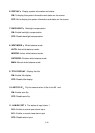
RELAY
JP5
Video +
Video -
RS485 +
RS485 -
AC24
AC24
JP5
1 ~ 9