


Genie Monochrome Series-GigE Vision Camera Installing the Genie Camera • 21
Connect the Genie Camera
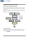
Connect a power supply to the Genie camera and an Ethernet cable from the Genie to the host computer. Once
communication with the host computer is started the automatic IP configuration sequence will assign an LLA IP
address as described in section "
Genie IP Configuration Sequence" on page 23, or a DHCP IP address if a DHCP
server is present on your network. The factory defaults for Genie is Persistent IP disabled and DHCP enabled with
LLA always enabled as per the GigE Vision specification. For additional information see "
IP Configuration Mode
Details" on page 77. See the next section "
Connectors" on page 21 for an overview of the Genie interfaces.
Connectors
The Genie has only two connectors:
• A single RJ45 Ethernet connector for control and video data transmitted to/from the host computer Gigabit
NIC. See "
Ruggedized RJ45 Ethernet Cables" on page 97 for secure cables.
• A single 12-pin Hirose male connector for camera power plus trigger, strobe and general I/O signals. The
suggested female cable mating connector is Hirose model HR10A-10P-12S.
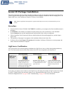
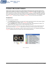
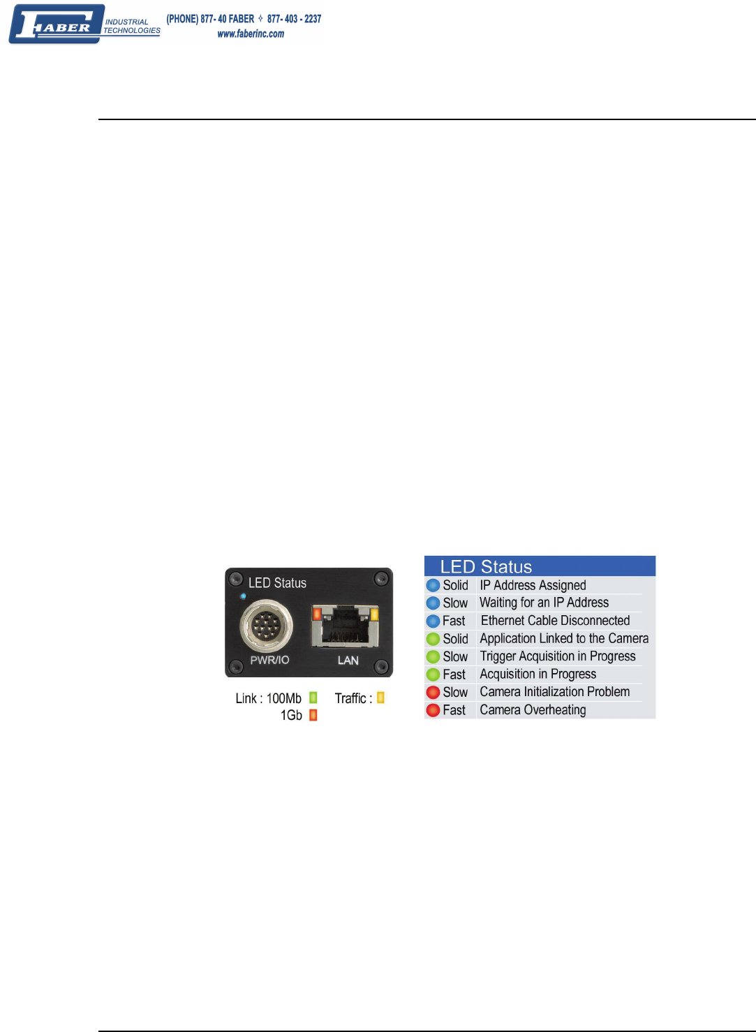
The Genie has one multicolor LED to provide a simple visible indication of camera state (see figure below and
section "
Status LED Codes" on page 22). Additionally the RJ45 has two LEDs for network status conditions.
The following figure of the Genie back end shows connector and LED locations. See "
Mechanical Specifications"
on page 89 for details on the Genie connectors and camera mounting dimensions.
Genie – Rear View