


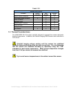
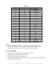

Table 2.2.1
Camera Pin # Frame Grabber Pin # Channel Link Signal
1 1 Inner shield
14 14 Inner shield
2 25 X0
15 12 X0+
3 24.0 X1-
16 11 X1+
4 23 X2-
17 10 X2+
5 22 Xclk
18 9 Xclk+
6 21 X3
19 8 X3+
7 20 SerTC+
20 7 SerTC-
8 19 SerTFG-
21 6 SerTFG+
9 18 CC1-
22 5 CC1+
10 17 CC2-
23 4 CC2+
11 16 CC3-
24 3 CC3+
12 15 CC4-
25 2 CC4+
13 13 Inner shield
26 26 Inner shield
Notes:
• Exterior overshield is connected to the shells of the connectors on both ends.
• 3M part 14X26-SZLB-XXX-0LC is a complete cable assembly, including connectors.
• Unused pairs should be terminated in 100 ohms at both ends of the cable.
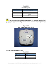
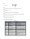
2.3 Power Supply
• The camera uses a single voltage input, normally set to 5.0V.
• Ripple and noise is required to be < 20 mV RMS.
• Power is supplied through a Hirose connector.
• When installing the mating connector, be sure to line up the slots. This action will assure that
you will not bend any of the pins.
Fairchild Imaging • CAM/CMOS-2K.LS Line Scan Camera User’s Manual • Rev C• 12 of 42