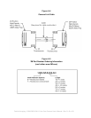
REFERENCE A
Camera Link
TM
Introduction
Camera Link is a Protocol that is Implemented in Channel Link Hardware
Camera Link is a communication interface for machine vision. The interface extends the underlying
technology of Channel Link to provide a specification more useful in this application.
For years, the scientific and industrial digital video market has lacked a standard method of
communication. Both frame grabbers and camera manufacturers developed products with different
connectors, making cable production difficult for manufacturers and very confusing for consumers.
A connectivity standard between digital cameras and frame grabbers has been long overdue and
will become even more necessary as data rates continue to increase.
Increasingly, diverse cameras and advanced signal and data transmissions have made a
connectivity standard like Camera Link a necessity. The Camera Link interface will reduce support
time, as well as the cost of that support. The standard cable will be able to handle the increased
signal speeds, and the cable assembly will allow customers to reduce their costs through volume
pricing.
Channel Link is a Widely-Used Signaling Method
National Semiconductor initially developed the Channel Link technology for flat-panel displays, and
based it on the LVDS physical layer. This technology was then extended for general-purpose data
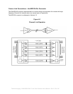
transmission. Channel Link is built up of sets of driver and receiver pairs. Each driver set accepts 28
single-ended data signals and an accompanying single-ended clock. This data is serialized 7:1, and the
resulting four data streams and clock signal are driven over five LVDS pairs. The receiver accepts these
five signals and drives the full 28 bits and clock signal to its output pins as shown in Figure A.1.
Channel Link's transmission method requires fewer conductors to transfer data and allow for a smaller
connector, which is important for compact cameras such as the CAM/CMOS – 2K.LS
The Channel Link chipset provides data transmission rates up to 2.38 Gbit/sec.
Channel Link uses LVDS, a Low-Voltage Differential Signaling Standard
Low Voltage Differential Signaling (LVDS) is a high-speed, low-power general purpose interface
standard. The standard, known as ANSI/TIA/EIA-644, was approved in March 1996. LVDS uses
differential signaling, with a nominal signal swing of 350mV differential. The low signal swing decreases
rise and fall times to achieve a theoretical maximum transmission rate of 1.923 Gbps into a lossless
medium. The low signal swing also means that the standard is not dependent on a particular supply
voltage. LVDS uses current-mode drivers, which limit power consumption. The differential signals are
immune to up to ±1 V common volt noise.
Fairchild Imaging • CAM/CMOS-2K.LS Line Scan Camera User’s Manual • Rev C• 36 of 42


