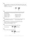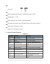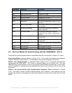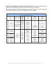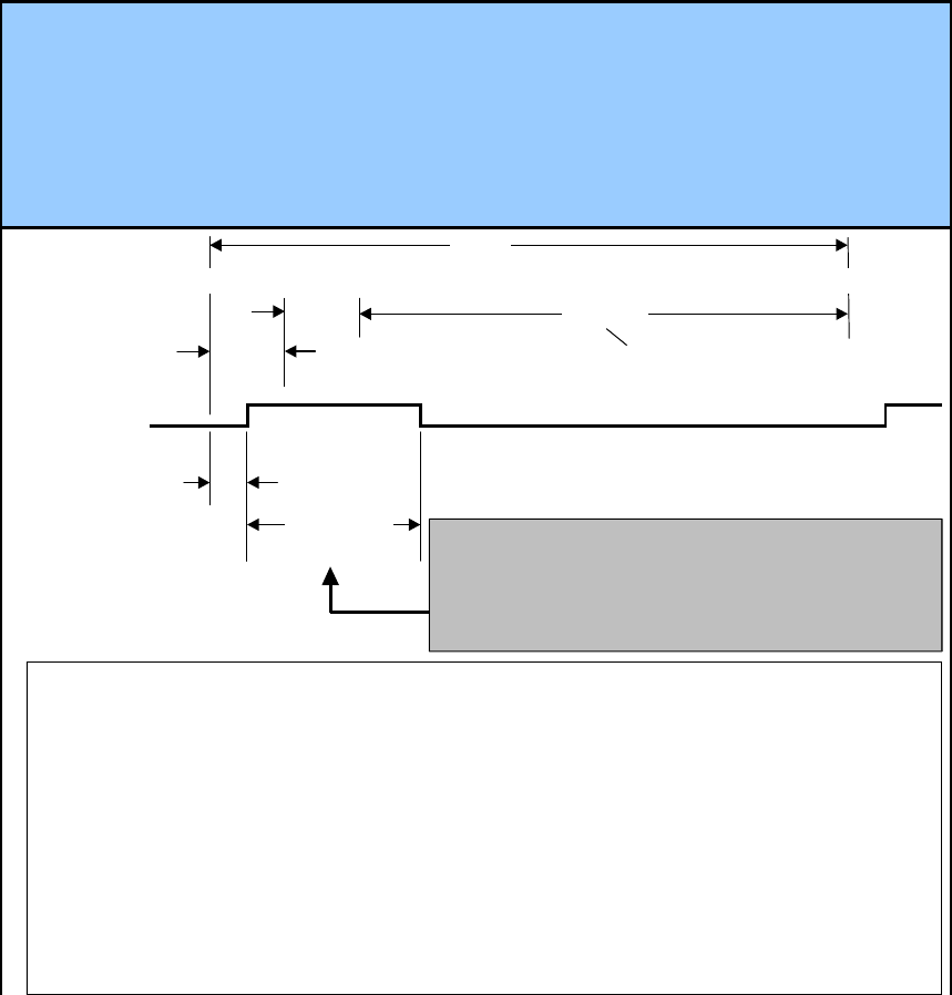
LineValid
Camera Output
Notes specific to this mode
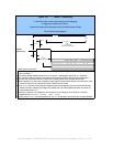
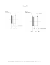
1 The camera is not triggered -- instead, the camera itself synchronizes the system. This is the default mode
set by the factory
2
The camera internally initiates readout of line "n" on its own. LineValid goes high a time "t
XFR
" afterwards
3 The user must synchronize motion of the material moving past the camera to the camera's LineValid output
4 The user must synchronize collection of data in the PC frame grabber to the LineValid camera output
5 While LineValid is high, data may be sampled on rising edges of Camera Strobe Output for the 2048 clock cycles
of readout as shown in the inset above; this is the same for all four modes
6
A time "t
Initiation
" after the camera internally initiates the readout-and-integration cycle, the camera also internally
initiates pixel reset; Integration then begins time "tReset" later, with this integrated information to be read out
in the subsequent line "n+1"
7 The factory-set default is for integration to run until the end of the line period, which results in a maximum
integration time "t
IntegrationMax
" = "t
LinePeriod
" - "t
Reset
" - "t
Initiation
".
8
The line period "t
LinePeriod
" and the integration time "t
Integration
" are selected by the user with the Command Software
Figure 3.4.1 -- Mode 1: Freerunning
...in this basic mode, usually used for diagnostics & debugging,
no triggering is applied to the camera...
...instead, the camera drives the system with the LineValid Camera Output.
The Line Period and Integration
t
XFR
t
LinePeriod
t
Readout
2048 Clock Cycles
t
Reset
t
IntegrationMax
t
Initiation
n
n+1
Data Camera Output
Strobe Camera Output
Line Valid Camera Output
1 2 3 1023 1024
may be shortened
with the Command Software
Fairchild Imaging • CAM/CMOS-2K.LS Line Scan Camera User’s Manual • Rev C• 21 of 42


