


Camera body 503CW
Adjustment
January 2001
Revision 1
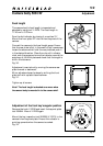
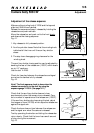
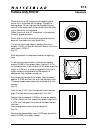
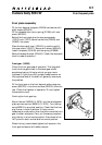
Check the mirror 45
o
angle using the sighting tube
which fits in the holder on the gauge. Tighten the
locking screw. Shine a light source towards the oval
cut-out in the upper part of the tube so that the white
ring of the ocular is illuminated.
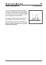
When the mirror is at 45
o
the pattern in the sighting
tube will appear as shown.
Check that the inner white circle is symmetrical and
does not lie outside the inner black field.
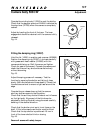
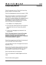
The mirror level is adjusted by bending the mirror
support (13121) on the left hand wall and/or the mirror
catch lever (13356-1).
Fig. 52.
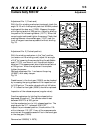
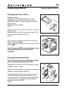
After adjustment is completed remove the sighting
tube.
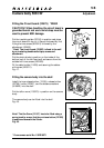
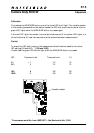
To adjust the screen position there are four special
screws (21606) in the screen frame. Use key V-4704
for the adjustment. Each rotation of the screw alters the
height by 0.35 mm. A cross is engraved on the tool’s
upper surface to help determine the amount of
adjustment that has been carried out.
First check the flatness of the screen. Use the screen
adapter V-4705 and the ruler with the indicator clock.
The same measurement should be obtained at all four
corners.
Fig. 53.
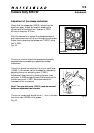
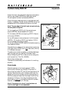
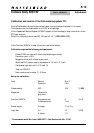
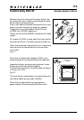
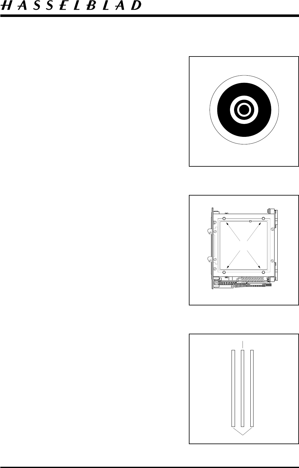
Then fit tool V-4151 into the camera’s front bayonet
plate. The tool should be powered by 6 volt DC.
Position the microscope V-2236 on the screen adapter
V-4705. Adjust (all four screws) the screen height with
V-4704 until the green line is central between the two
red lines.
Use the engraved cross on tool as reference.
Fig. 54.
Remove the camera body from V-2229 and secure the
screws (21606) with safety lacquer.
5:10
Fig. 52
Fig. 53
Fig. 54
21606
Green line
Red lines