


6
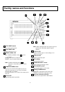
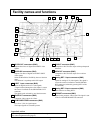
Facility names and functions
23
Genlock connectors (BNC)
Input for tri-level sync signal or black burst signal
for genlock operation.
24
AC IN connector
Input for AC power supply.
25
FG terminal
Frame ground terminal.
26
Fiber connector
Connect Fiber cable.
27
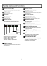
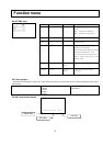
Receiver Level LED
The strength of the arriving light signal via fiber
cable is indicated by position of lighting LED.
ndicate the receiver level approximately
GREEN1: -3dBm to -8dBm (Normal)
GREEN2: -8dBm to -11dBm
YELLOW: -11dBm to -14dB (Warning)
RED: under -14 dB (Alarm)
28
REMOTE1 connector
Connection for the optional camera control panel or
setup control unit.
29
RS-232C connector
Use for camera control via RS-232C.
30
REMOTE2 connector
Connection for the optional camera control panel or
setup control unit.
31
TALLY OUT connector
Contact outputs for tally signals.
32
COMMUNICATION connector
Intercom and tally inputs from external system.
33
MIC REMOTE connector
This connector is used to select the MIC1 and
MIC2 amplifier gains.
34
WFM CONTROL connector
This connector is used to select the display mode of
the waveform monitor.
35
MIC OUT1 connector (XLR 3 pin)
Outputs MIC1 audio signals from a camera or the
CA-HF1000 at 0 dBm.
36
MIC OUT2 connector (XLR 3 pin)
Outputs MIC2 audio signals from the CA-HF1000
at 0 dBm.
37
RJ-45 connector
This connector is used to connect expanded
functions such as a remote controller.
38
TALLY CONTACT/VOLTAGE
The TALLY input can be contact or voltage supply.
Set the TALLY switches according to the systems
connected to CU-HD1000 rear panel
COMMUNICATION connector.
GREEN1
GREEN2
YELLOW
RED