


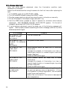
14. OUTPUT/SYNC
On this menu screen, you can make signal changeover for output to the D-SUB connector
and phase adjustment for external synchronization.
1) OUTPUT : Output mode changeover
R, G, B㧦The R, G and B video signals are output to the D-SUB connector.
Y, R-Y, B-Y㧦The Y, R-Y and B-Y signals are output to the D-SUB connector.
Y/C㧦The Y/C and VBS signal is output to the D-SUB connector.
2) COLOR BAR : Color bars ON/OFF
3) MONO : Monochrome (black and white) ON/OFF for the video output signal from the
VIDEO connector
Set to ON for monochrome. Setting ineffective during color bar.
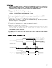
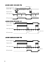
4) Sync/HD out : Selects sync signal output from the rear panel multi connector.
5) SYNC ON G : G video signal synchronization ON/OFF (In the R/G/B mode only)
When output is RGB with Sync on and G on, Sync is added to the G video signal.
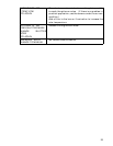
6) GL IN : Impedance changeover of input to the GL IN connector.
HIGH : The high impedance level is provided.
75ǡ : An impedance of 75 ohms is provided.
Note: When power to the camera is turned off, the high impedance level is provided.
So, do not use this function in a system where power is turned off for the
camera unit only.
7) GL MODE : GL signal input changeover
VBS : The VBS signal or BBS (black burst) signal is input as an external
synchronizing signal.
HD/VD : The HD/VD signal is input as an external synchronizing signal.
Note: During external sync with HD and VD signals, be sure to use either RGB or Y,
B-Y, R-Y output signals. Although VBS and Y/C output signals are also
produced, these cannot be used as normal output signals.
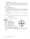
8) SC.COARSE : Coarse adjustment of subcarrier phase
Using the L or R button, select one of the following phases; 0º, 90º, 180º and 270º.
29