


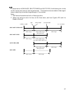
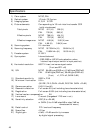

Input/Output Signals
1. Input signal conditions
1) Genlock input (MULTI connector)
㨯 VBS 1.0 Vp-p r3 dB or black burst/75 ǡ or high (BNC)
(sync 0.3 r0.1 Vp-p, burst 0.3 r0.1 Vp-p)
㨯 HD/VD 2 to 5 Vp-p, negative (D-sub connector)
Note: Genlock input and Sync output are selected by internal input/output switch.
2) External trigger input (MULTI connector)
Ext Trig Low 0 VDC, High 2 to 5 VDC
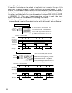
3) Serial data (REMOTE connector)
1.5 Vp-p r3 dB/High (when connected to RC-Z3, JU-C20, JU-Z2)
RS-232C level (when connected to personal computer)
Note: Set internal switches according to connected equipment.
A level converter JU-C20 is required if controlling the camera from a personal
computer via RS-232C interface over a distance more than approx.15 meter.
2. Output signal ratings
1) Component video output (VIDEO, MULTI connector)
VBS 1.0 Vp-p/75㱅
2) Y/C output (MULTI connector)
Y: 1.0 Vp-p/75ǡ
C: NTSC 0.286 Vp-p (burst)/75ǡ
PAL 0.3 Vp-p (burst)/75ǡ
3) Component output (MULTI connector)
Y : 1.0 Vp-p/75ǡ
R-Y: 0.7 Vp-p/75ǡ
B-Y: 0.7 Vp-p/75ǡ
4) RGB output (MULTI connector)
R: 0.7 Vp-p/75ǡ
G: 0.7 Vp-p/75ǡ
B: 0.7 Vp-p/75ǡ
Note: YC/VBS, component and RGB MULTI connector outputs are selected by
menu.
5) Sync outputs (MULTI connector)
HD: 2 Vp-p/75ǡ
VD: 2 Vp-p/75ǡ
Sync: 2 Vp-p/75ǡ
Note: Genlock input and Sync output are selected by internal input/output
switch.
50