


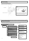
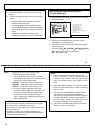
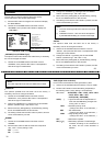
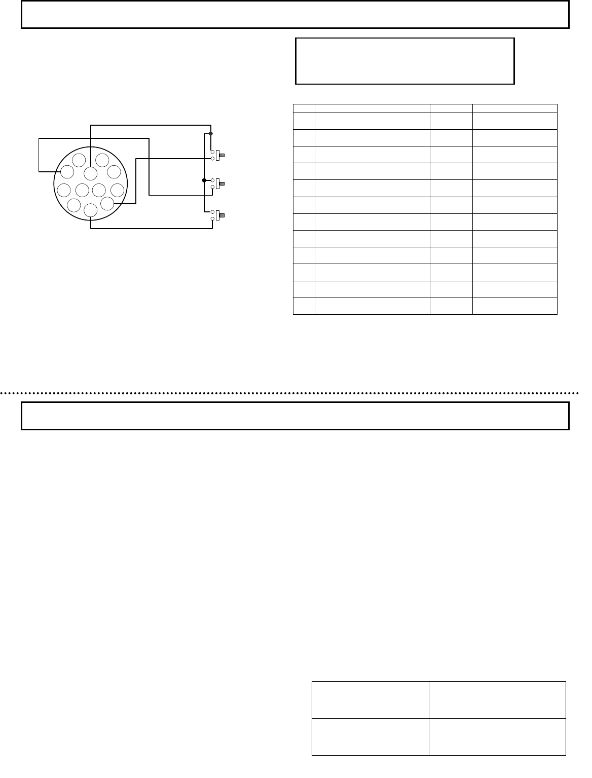
External key switch connections for remote operation
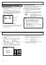
Remote menu operation
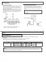
1.Color system NTSC
2.Pickup element 1/2-inch progressive scan frame
interline CCD( with on-chip microlenses )
Total pixels 680(H)
× 500(V)
Effective pixels 658(H)
× 489(V)
Scanning area 6.58(H)
× 4.89(V)mm
Sell size 10.0(H)
× 10.0(V)μm
3.Scanning system 2:1 interlace
4.Scanning frequency Hor. 15.734kHz
Ver. 59.94Hz
5.Sync system internal
6. Video signal output KP-DE500:VBS1.0Vp-p/75Ω
KP-E500:VS1.0Vp-p/75Ω
7. Signal processing Digital processing ( input 10 bits )
8. S/N( Y signal ) More than 50dB
(AGC,enhancer and gamma OFF)
9. Resolution( Y signal at center ) Hor. :480 lines
Ver. :350 lines
10.Minimum illumination
KP-DE500
0.009 lx ( Color, F1.4, AGC ON, SENS UP OFF, 50IRE )
0.0005 lx( Monochrome, F1.4, AGC ON, SENS UP OFF, 50IRE )
0.00015lx(Color 64 time accumulation, F1.4, AGC ON, 50IRE)
0.000008lx
(Monochrome 64 time accumulation, F1.4, AGC ON, 50IRE)
KP-E500
0.0003 lx
(Monochrome, F1.4, AGC ON, SENS UP OFF, 50IRE )
0.000005 lx
(Monochrome 64 time accumulation, F1.4, AGC ON, 50IRE)
11. Sensitivity setting AGC OFF/ON(Factory setting is1/60)
Manual Gain Adjustable at AGC OFF
Limit Gain Adjustable at AGC ON
12. Electronic shutter speeds
Selectable in 7 steps & AES
( Factory setting is 1/60 )
1/60,1/100,1/125,1/250,1/500,1/1000,1/2000
AES:From 1/60 second to 1/2000 second
13.
Integration multiple [SENS UP] setting
:Automatic or Manual (fixed) ( Factory setting is OFF )
Automatic : 2,4,6,8,10,12,16,32,64 times
Manual : 2,4,6,8,10,12,16,32,64,88,128 times
14. Backlight compensation ON/OFFswitchable
Sensing area:selectable from 9 areas
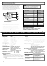
15.Auto-iris lens outputs
Video signal
Input type lens
Luminance signal
1.0Vp-p/high impedance
Power supply 12V DC 40mA
Iris control voltage input
(galvanometer)
Coupling coil impedance
Damper:1150Ω±10%
Drive:190Ω±10%
Specifications
32
33
A
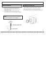
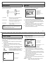
n optional remote plug is available to enable operating
the camera mode and set buttons by remote control.
Confirm the plug is properly wired as indicated in the
figure and connect it to the rear panel Remote connector.
Do not connect anything to the unused Pins.
1
5
3
8 2
9
10
12 11
6
7
4
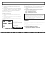
Remote plug(option)
UP
DOWN
SET
Pin Signal Abbrev. Remarks
1 Not connected N.C. Do not connect
2 Serial data input Tx Connect to RS-232C
data terminal
3 Serial data output Rx Connect to RS-232C
data terminal
4 Up key UP Key switch connection
5 Down key DOWN Key switch connection
6 Not connected N.C. Do not connect
7 Not connected N.C. Do not connect
8 Set key SET Key switch connection
9 Not connected N.C. Do not connect
10 GND GND Connect to RS-232C
ground
11 Not connected N.C. Do not connect
12 Not connected N.C. Do not connect
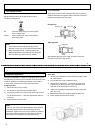
Remote operation with RS-232C
Signals 2, 3 and 10 can be used for control by personal
computer. Consult dealer for retailed information.
Keep the distance between the remote plug and
external key switches to less than about 2 meters.
Disconnect the remote plug from the camera Remote
connector when not using the key switches.
NOTE
Be sure to switch off the camera power before
connecting or disconnecting the remote plug.