


CV-L105
- 1 -
Table of Contents
1. General ........................................................................................................2
2. Standard Composition ......................................................................................2
3. Main Features ................................................................................................2
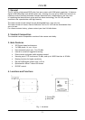
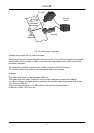
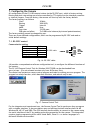
4. Locations and Functions ...................................................................................2
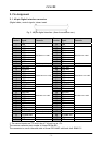
5. Pin Assignment...............................................................................................3
5.1. 68-pin Digital interface connector ............................................................................. 3
5.2. 6-pin Hirose connector (Power) ................................................................................ 4
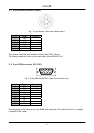
5.3. 9-pin DSUB connector (RS-232C)................................................................................ 4
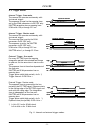
5.4. Input and Output Circuits........................................................................................ 5
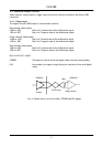
5.4.1. Video output................................................................................................ 5
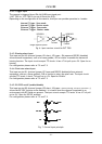
5.4.2. Trigger input................................................................................................ 6
5.4.3. Binning select input ....................................................................................... 6
5.4.4. Pixel rate select input .................................................................................... 6
5.4.5. RS-232C on/off (enable/disable)........................................................................ 6
6. Functions and Operations .................................................................................7
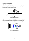
6.1. Principle of operation............................................................................................ 7
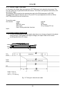
6.2. Trigger modes ..................................................................................................... 9
6.2.1. Internal Trigger. Scan mode. ...........................................................................10
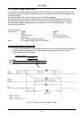
6.2.2. Internal Trigger. Shutter mode. ........................................................................11
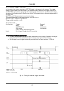
6.2.3. External Trigger. Scan mode............................................................................12
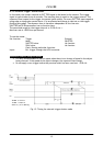
6.2.4. External Trigger. Shutter mode. .......................................................................13
6.3. Other functions...................................................................................................14
6.3.1. Binnig .......................................................................................................14
6.3.2. Pixel rate...................................................................................................14
6.3.3. RS-232C on/off ............................................................................................14
6.3.4. Offset and Gain ...........................................................................................14
6.3.5. LED on rear ................................................................................................14
7. Configuring the Camera.................................................................................. 15
7.1. RS-232C control. .................................................................................................15
7.1.1. Clock Select................................................................................................16
7.1.2. Binning......................................................................................................16
7.1.3. Trigger Mode...............................................................................................16
7.1.4. Shutter/Scan Mode .......................................................................................16
7.1.5. Shutter/Scan Time........................................................................................16
7.1.6. Gain and offset adjustment.............................................................................17
7.1.7. Communication and files ................................................................................17
7.2. Configuration via I/F connector and jumpers ...............................................................18
7.3. Potentiometers and jumpers placing .........................................................................18
8. External Appearance and Dimensions ................................................................ 19
9. Specifications .............................................................................................. 20
9.1. Specifications table..............................................................................................20
9.2. Spectral Sensitivity ..............................................................................................20
10. Users Record.............................................................................................. 21