


CV-L105
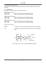
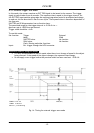
5.4.2. Trigger input
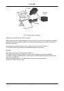
The camera is triggered by an EIA-644 LVDS input signal pair.
(+EXT TRIG in/ -EXT TRIG in (on pin #19 and pin #53)).
Depending on the configuration of the camera, this input can provide operation in 4 modes:
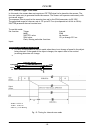
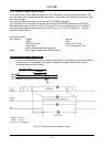
Internal Trigger. Scan mode.
Internal Trigger. Shutter mode.
External Trigger. Scan mode.
External Trigger. Shutter mode.
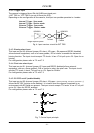
DS90C032
DS90C031
100
Camera
Image capture system
Twisted
Fi
g. 6.
In
put
r
ece
i
ve
r
c
ir
cu
i
t
f
o
r
EXT
TRI
G
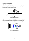
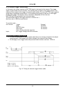
5.4.3. Binning select input
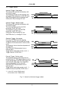
This input on pin #10 (internal jumper JP1=short, JP2=open, JP4=open and RS232C disabled)
allows external equipment, such as a frame grabber, PLD or similar to enable the horizontal
binning function. The input circuit accepts TTL levels. It has 4.7 kΩ pull up to +5V. Open for no
binning.
For configuration please refer to 7.2 and 7.3.
5.4.4. Pixel rate select input
This input on pin #31 (internal jumper JP 5 open and RS232C disabled) allows external
equipment, such as a frame grabber, PLD or similar to select the pixel rate. The input circuit
accepts TTL levels. It has 4.7 kΩ pull up to +5V. Open for 30 MHz.
For configuration please refer to 7.2 and 7.3.
5.4.5. RS-232C on/off (enable/disable)
This input on pin #30 (internal jumper JP3=short, JP4=open.
(Factory settings, JP3=open, JP4=short.) )
allows the RS-232C function to be disabled. It is useful when the camera is operated in an
environment with RFI fields are present. The input circuit accepts TTL levels. It has 4.7 kΩ pull
up to +5V. Open for RS232C enabled.
For configuration please refer to 7.2 and 7.3.
JP1
#10
JP2
Bin
JP3
#30
JP4
RS-232
#31
JP5
Clk
JP1
#10
JP2
Bin
JP1
#10
JP2
Bin
JP3
#30
JP4
RS-232
JP3
#30
JP4
RS-232
#31
JP5
Clk
#31
JP5
Clk
Fig. 7. Control input principle
- 6 -