


Page 4
TM-2016-8 and TM-2016-8CL Progressive Scan Shutter Camera
Introduction
1.4 System Configuration
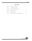
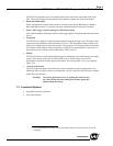
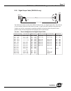
FIGURE 1. TM-2016-8 System Configuration
Figure 1 below presents a typical system configuration for the TM-2016-8 camera.
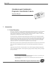
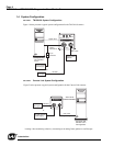
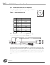
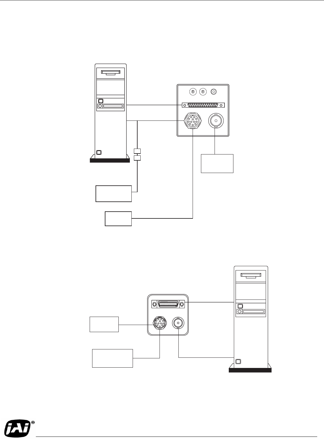
FIGURE 2. Camera Link System Configuration
Figure 2 below presents a typical system configuration for the Camera Link cameras.
Computer with
frame-grabber
board
analog frame
grabber
PD-12 (series)
power supply
Power and
Ext. Sync
Digital cable
SHUTTER MODE
UP
DOWN
POWER
VIDEO
0
9
8
7
6
5
4
3
1
2
1
0
F
E
D
C
B
A
2
3
4
5
6
7
8
9
DIGITAL
BNC cable
12P-02S
RS-232B-12
cable in
CS-232E kit
1
2
3
4
5
6
9
8
7
11
12
10
12-pin
connectors
OR
CAMERA LINK
POWER VIDEO
Computer with
Camera Link™
frame grabber
PD-12P (series)
power supply
Power and
Ext. Sync
26CL-02-26
12P-02S
or
1
2
3
4
5
6
9
8
7
11
12
10
BNC Cable
Analog Framegrabber
Cable
Camera Link Cable
*Analog video monitoring is done by connecting to an analog frame grabber or oscilloscope.