


Page 15
TM-2016-8 and TM-2016-8CL Progressive Scan Shutter Camera
Operation
3 Operation
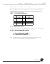
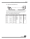
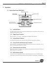
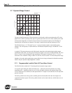
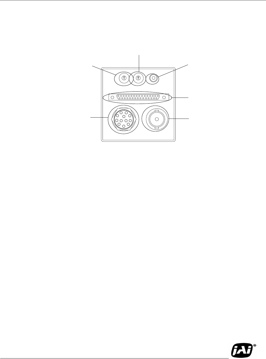
3.1 Camera Rear Panel (TM-2016-8)
3.1.1 Up/Down Switch
The Mode Selection switch works in conjunction with the Up/Down switch. Refer to Table 6 above for
information on the Up/Down switch.
3.1.2 Digital Output Connector
Refer to Section 2.2.2 (c on page 7 for information on the digital output connector.
3.1.3 Analog Output Connector
The TM-2016-8 camera has a BNC connector on the rear panel to output analog video data.
3.1.4 Power, RS-232, and External Sync Connector
Refer to Section 2.2.2 on page 6 for information on the power and external sync, and Section 2.2.4 on
page 10 for information on the RS-232 connector.
3.1.5 Shutter Speed Control Switch
Please refer to Section 2.2.3 on page 10 for information on the Shutter Speed Control dial. The factory
default settings are at 0 (no shutter).
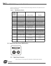
3.1.6 Mode Selection Switch
Various modes can be implemented with the rear panel Mode Selection switch. The Mode Selection
switch works in conjunction with the Up/Down switch and RS-232 external control. Commands from
SHUTTER MODE
UP
DOWN
POWER
VIDEO
0
9
8
7
6
5
4
3
1
2
1
0
F
E
D
C
B
A
2
3
4
5
6
7
8
9
DIGITAL
1
2
3
4
5
6
9
8
7
11
12
10
Up/Down switch
Digital Output connector
Analog Output connector
Power, RS-232, and
External Sync Connector
Mode Selection switch
Shutter Speed
Control switch