


76
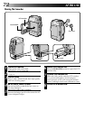
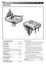
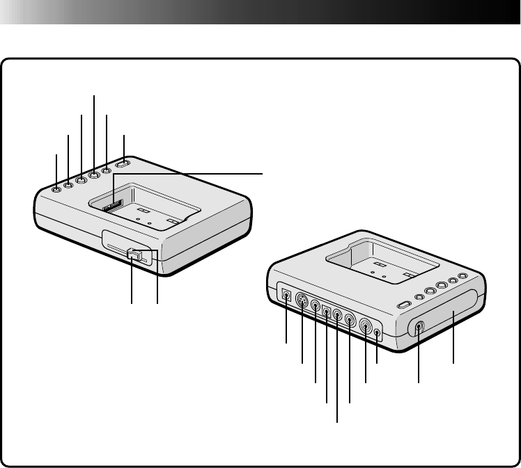
Docking Station
1
26
7
8
35
4
9
0
!&(
@^ *
#%
$
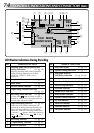
^Printer connector
•Connects to the optional video printer's video
output connector. This allows you to watch the
image from the video printer on the LCD
monitor without connecting to a television
(੬ pg. 49).
• When the VIDEO cable is connected to this
connector, the date and time code are not
displayed on the LCD monitor. To print out a
scene with its date, connect the video printer's
video output connector to a TV and operate
the video printer using a TV monitor.
& JLIP jack (joint Level Interface Protocol)
• It is used to connect the camcorder to a device
such as a personal computer.
For further detail consult your nearest JVC
dealer. Information (in English) is also available
at our home page: http://www.jvc-victor.co.jp/
* EDIT jack ........................................... ੬ pg. 60
( Remote control sensor .......................੬ pg. 56
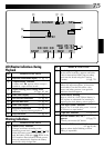
1 Fast-Forward (FF) button
2 Rewind (REW) button........................ ੬ pg. 62
3 STOP button ...................................... ੬ pg. 58
4 PLAY button ...................................... ੬ pg. 56
5 PAUSE button
6 EDIT button....................................... ੬ pg. 62
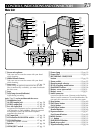
7 Multi connector
Connect to the camcorder’s multi connector. To
avoid malfunction, do not touch this connector.
8 RELEASE button ................................. ੬ pg. 51
9 Lock lever.......................................... ੬ pg. 51
0 DC input jack .................................... ੬ pg. 51
! S-Video output jack ........................... ੬ pg. 52
Outputs S-Video signal.
@ Video output jack .............................. ੬ pg. 52
# DC output jack
For dealer use.
$ Audio output jack [L] ........................ ੬ pg. 52
% Audio output jack [R] ........................ ੬ pg. 52
CONTROLS, INDICATIONS AND CONNECTORS
(Cont.)