


13
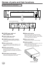
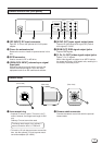
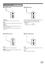
Camera control unit (rear panel)
1 [DC INPUT] DC input connector
Input DC 12 V from the optional AA-V112U power
adaptor.
2 Cover for extension slot
Remove the cover to install an optional device in this
slot.
3 SCSI connector
Used to connect a ZIP or MO drive.
4 [GENLOCK INPUT] external sync signal
input jack
Reference signal input jack used to connect the
camera video output signal in sync with other
equipment such as an HD camera and switcher.
5 [SYNC OUT] sync signal output jacks
Outputs HD (horizontal drive signal)/VD (vertical
drive signal)/C. SYNC.
6 [RGB OUT] RGB signal output jacks
Outputs RGB signals.
7 [Y, PB, PR OUT] video signal output jacks
Output Y, PB, PR signals.
When video signals are output to an HDTV monitor,
the screen will have a 16:9 aspect ratio, resulting in a
horizontally extended picture.
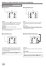
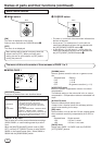
Camera head
1 Lens mount ring
• A special C mount is used. The form is for C
mount, however, the flange back length is 28.0
mm.
Ordinary C mount cannot be used.
The flange back length of an ordinary C
mount conversion lens is 17.526 mm.
• To install a 1/2-inch bayonet mount conversion
lens, use the optional 1/2-inch bayonet mount
conversion adapter (GL-V62U) .
2 Camera cable connector
Connect the camera control unit with the optional
camera cable.
1
2
(Front view)
(Rear view)
(Side view)
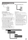
DC-IN
GEN-LOCK IN
SYNC OUT
VS/C. SYNC
(
75Ω
)
HD
VD
C. SYNC
HD OUT
G
B
Y
P
B
RPR
12 45673