


33
A
B
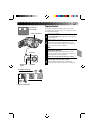
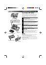
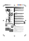
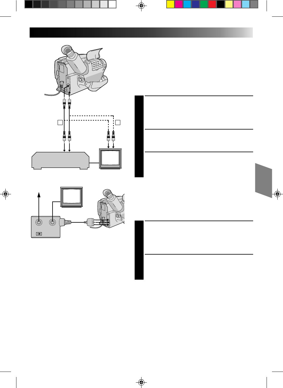
There are three basic types of connections. When making
the connections, refer also to your VCR and TV
instruction manuals.
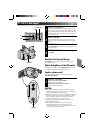
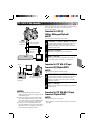
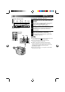
Connection To A VCR [A]
(Editing, Dubbing and Playback)
NOTE:
Use the optional Audio and Video cables.
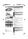
CONNECT CAMCORDER TO VCR
1
As shown in the illustration on the left, connect the
optional Audio and Video cables between the
AUDIO and VIDEO connectors on the camcorder
and those on the VCR.
SUPPLY POWER
2
Turn on the camcorder, the VCR and the TV.
SELECT MODE
3
Set the VCR to its AUX input mode, and set the TV
to its VIDEO mode or channel 3 or channel 4.
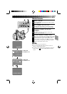
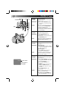
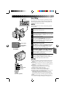
Connection To A TV With A/V Input
Connectors [B] (Playback ONLY)
NOTE:
Use the optional Audio and Video cables.
CONNECT CAMCORDER TO TV
1
As shown in the illustration on the left, connect the
optional Audio and Video cables between the
AUDIO and VIDEO connectors on the camcorder
and those on the TV.
SELECT MODE
2
Set the TV to its VIDEO or AV mode (as specified in
its instructions).
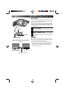
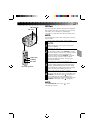
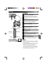
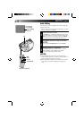
Connection To A TV With NO A/V Input
Connectors (Playback ONLY)
NOTE:
Use the optional RF-V5U RF unit.
* Refer to the RF-V5U instruction manual for connection
procedure.
NOTES:
●
It is recommended to use the AC Power
Adapter/Charger as the power supply instead
of the battery pack.
●
To monitor the picture and sound from the
camcorder without inserting a tape, set the
camcorder’s power switch to CAMERA, then
set your TV to the appropriate input mode.
●
If you have a TV or speakers that are not
specially shielded, do not place the speakers
adjacent to the TV as interference will occur
in the camcorder playback picture.
Aerial
RF unit RF-V5U
(optional)
To AUDIO, VIDEO and
DC OUT connectors
VCR
PLAYBACK
Basic Connections
To AUDIO
and VIDEO
connectors
Audio and Video
cables (optional)
To AUDIO and
VIDEO IN
connectors