


GETTING STARTED
GETTING STARTED
EN 7
MasterPage: Start_Right
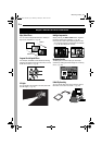
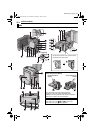
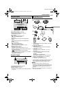
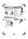
Controls
a Menu Button [MENU] (੬ pg. 27)
b Sub Zoom Buttons [T/W] (੬ pg. 16)
Speaker Volume Control [VOL. +, –] (੬ pg. 17)
c Snapshot Button [SNAPSHOT] (੬ pg. 21, 32)
d Recording Start/Stop Button (੬ pg. 15)
e VIDEO/MEMORY Switch (੬ pg. 12)
f Power Zoom Lever [T/W] (੬ pg. 16)
g Diopter Adjustment Control (੬ pg. 13)
h Power Switch [A, M, PLAY, OFF] (੬ pg. 12)
i Lock Button (੬ pg. 12)
j Set Button [SET] (੬ pg. 27)
k Stop Button [8] (੬ pg. 17)
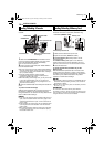
Backlight Compensation Button [BACK LIGHT]
(੬ pg. 33)
Down Button [ ] (੬ pg. 27)
l Rewind Button [
3
] (੬ pg. 17)
Night Button [NIGHT] (੬ pg. 32)
Left Button [ ] (੬ pg. 27)
m Play/Pause Button [4/9] (੬ pg. 17)
Manual Focus Button [FOCUS] (੬ pg. 32)
Up Button [ ] (੬ pg. 27)
n Fast-Forward Button [
5
] (੬ pg. 17)
LED Light Button [LIGHT] (੬ pg. 31)
Right Button [ ] (੬ pg. 27)
o Information Button [INFO] (੬ pg. 23)
E-Mail Clip Recording Button [E-MAIL] (੬ pg. 24)
p Index Button [INDEX] (੬ pg. 23)
Navigation Button [NAVI] (੬ pg. 36)
q Thumbnail Storing Button [NAVI STORE] (੬ pg. 36)
r D.S.C. Playback Select Button [SELECT]
(੬ pg. 22, 23)
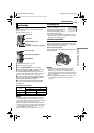
s Battery Release Switch [BATT.RELEASE] (੬ pg. 11)
t Cassette Open/Eject Switch [OPEN/EJECT]
(੬ pg. 14)
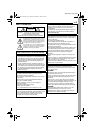
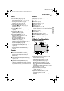
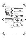
Connectors
The connectors are located beneath the covers.
U Microphone connector [MIC] (੬ pg. 30, 40)
(An optional microphone can be used during video
recording and audio dubbing. To stabilize the
microphone, use of an optional shoe adapter is
recommended.)
V USB (Universal Serial Bus) Connector (੬ pg. 39)
W S-Video/Audio/Video Input/Output Connector [AV]
(੬ pg. 18, 37, 42)
X DC Input Connector [DC] (੬ pg. 11)
Y Digital Video Connector [DV IN/OUT] (i.Link*)
(੬ pg. 38, 39)
* i.Link refers to the IEEE1394-1995 industry specification
and extensions thereof. The logo is used for products
compliant with the i.Link standard.
Indicators
DPOWER/CHARGE Lamp (੬ pg. 11, 15)
ETally Lamp (੬ pg. 15, 29)
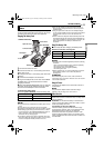
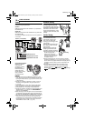
Other Parts
cViewfinder (੬ pg. 13)
dLCD Monitor (੬ pg. 15, 16)
eBattery Pack Mount (੬ pg. 11)
fGrip Strap (੬ pg. 13)
gSpeaker (੬ pg. 17)
hStereo Microphone (੬ pg. 40)
(When using an optional conversion lens, it may cover
this area. In this case, use of an optional microphone
is recommended.)
iLED Light (੬ pg. 31)
jRemote Sensor (੬ pg. 19)
kCamera Sensor
lTripod Mounting Socket (੬ pg. 13)
mMonitor Latch
nCard Cover [MEMORY CARD] (੬ pg. 14)
oCassette Holder Cover (੬ pg. 14)
pLens
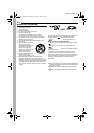
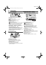
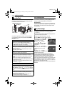
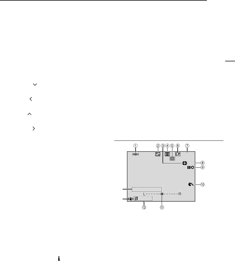
LCD Monitor/Viewfinder Indications
During Video Recording Only
a Navigation Indicator (੬ pg. 35)
b Selected Wipe/Fader Effect Indicator (੬ pg. 34)
c Tape Running Indicator (੬ pg. 15)
(Rotates while tape is running.)
d Selected Wide Mode Indicator (੬ pg. 29)
e Thumbnail Storing Indicator (੬ pg. 35)
f Recording Speed Mode (SP/LP) (੬ pg. 28)
g Tape Remaining Time (੬ pg. 15)
h REC: (Appears during recording.) (੬ pg. 15)
PAUSE: (Appears during Record-Standby mode.)
(੬ pg. 15)
i Insert Editing/Insert Editing Pause Mode (੬ pg. 40)
j Wind Cut Indicator (੬ pg. 29)
k Auxiliary Microphone Level Indicator
(Appears when an optional microphone is connected.
੬ pg. 30, “AUX MIC” )
l Time Code (੬ pg. 30, 31)
m Digital Image Stabilizer (“DIS”) (੬ pg. 28)
n Sound Mode Indicator (੬ pg. 28)
(Appears for approx. 5 seconds after turning on the
camcorder.)
SOUND
12
BIT
1h40m
r
e
15:55
REC
GR-DX97US.book Page 7 Monday, February 9, 2004 2:28 PM