


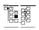
E-12
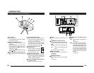
REC
PLAY
FFREW
REVERSE
PAUSE/
STILL
REC
CHECK
STOP/EJECT
COUNT/
CLOCK
TIME
MODE
TIMER
REC
AL/PL
RESET
MENU
VIDEO CASSETTE RECORDER
SHIFT/TRACKING
SET/V.LOCK
RESET
/CANCEL
OPERATE
SR-L910
OPE. LOCK
1
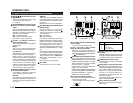
TO CAMERA
TO CAMERA
DATA I / O
DATA I / O
RX
RX
+
RX
RX
-
TX
TX
+
TX
TX
-
COM
COM
1234567 8
COM
COM
9/110/2
10/2
11/3
11/3
12/4
12/4
13/5
13/5
14/6 15/7
15/7
16/8
COM
COM
COM
COM
COM
COM
CAMERA
CAMERA
SW
UNIT
UNIT
ALARM
ALARM
AUTO
AUTO
431 2 875 6
2 3 4 5 6 7
8
1
MONITOR
MONITOR
OUTPUT
OUTPUT
MONITOR
MONITOR
SERIAL-2
SERIAL-2
SERIAL-1
SERIAL-1
VIDEO INPUT
VIDEO INPUT
VIDEO OUTPUT
VIDEO OUTPUT
OUTPUT
OUTPUT
2
1
ON
ON
2 3 4 5 6 7
8
POWER
OFF
AC INPUT
•••••
CAMERA
SW
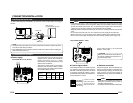
Remote Control Unit
RM-P2580
Time lapse VCR
MONITOR
MONITOR
CAM SW
OUT
VIDEO IN
COM
TO
CAMERA
MONITOR
OUTPUT 2
MONITOR
OUTPUT 1
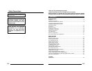
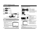
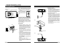
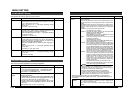
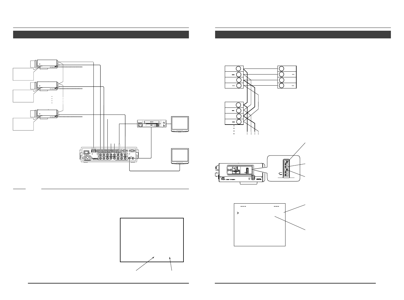
CONNECTION/INSTALLATION
RM-P2580 System
Ⅲ System with up to 8 cameras
Camera
TK-C1430
Camera
TK-C1430
Camera
TK-C1430
Camera 1
Camera 2
Camera 8
Control signal cable
Video signal cable
Power
cable
AC24V
or
DC12V
AC24V
or
DC12V
AC24V
or
DC12V
MONITOR screen
(example showing camera ID as “05”)
This is the connected example of the TK-C1430E.
When controlling with any system except the RM-P2580, execute proper settings using
switches and menu screens according to the systems used. (੬ Page 14)
PROT OOLDUPLEXID-05C :
“DUPLEX” should
be displayed.
The number shown in the
□□ part of ID-□□
should be correct.
MACHINE ID:1
(Menu screen)
RX TERM: OFF
(switch)
MACHINE ID:2
(Menu screen)
RX TERM: OFF
(switch)
MACHINE ID:8
(Menu screen)
RX TERM: ON
(switch)
MEMO
• When operating a system using the RM-P2580, several cameras (up to 16) can be con-
nected and used on one control signal cable. Consequently, an incorrect switch setting on
just a single camera will cause the entire system to work incorrectly.
• Confirm switch settings on the screen as follows.
q Confirm that the image from the camera to be checked
is displayed on the monitor.
w Tu rnOFF and then ON the AC power to the camera to
be checked.
e The camera begins the initial operation and characters
similar to those shown in the illustration on the right
appear on the monitor screen.
r Confirm that “DUPLEX” and “ID-□□” are displayed and
that the ID number is the correct number (the number
should be the same as the number of the VIDEO IN-
PUT terminal to which the camera is connected on the
rear panel of the RM-P2580).
t If wrong, set the camera ID again.
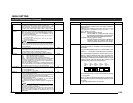
E-13
CAMERA
SETUP
SET
MENU
EXT TERM-OFF
INT/GL
DUPLEX
RX TERM-OFF
NOT USED
ON
LL
SIMPLEX
ON
EXT TERM-OFF
INT/GL
DUPLEX
RX TERM-OFF
NOT USED
ON
LL
SIMPLEX
ON
VIDEO
DC
IRIS
AWC
A RX
+
B RX
C TX
+
D TX
TX
+
A
TX B
RX
+
C
RX D
TX
+
A
TX B
RX
+
C
RX D
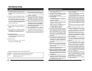
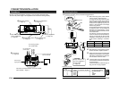
RM-P2580
Camera 2
control signal
connection terminals
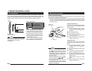
Connect:
Camera TX+ to RM-P2580 RX+
Camera TX– to RM-P2580 RX–
Camera RX+ to RM-P2580 TX+
Camera RX– to RM-P2580 TX–
The A BCD marks indicated on both the
camera terminals and the RM-P2580 termi-
nals facilitate correct connections. Connect
the terminals with identical marks.
Ⅲ Connecting the control signal cable
(Use a twisted-pair cable for connection. ੬ Page 17.)
Camera 1
control signal
connection terminals
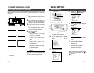
Ⅲ Setting the switches (੬ Page 10)
Select the synchronization method of the
camera image.
Set the switch on all cameras to LL (Line Lock)
and match with the V. PHASE.
(੬ Page 26.)
Set this switch to the DUPLEX
* If the setting is changed, be absolutely sure to
switch on the power again.
Set this switch to ON (signal termination ON)
only on the camera placed at the end of the
control signal cable.
Set to OFF on all other cameras.
Ⅲ Setting on the MENU screen (੬ Page 35)
* If the setting is changed, escape from the menu screen once, and definitely switch on the power again.
MACHINE ID setting switches
Set this item to match the RM-P2580 VIDEO
INPUT terminal number for each camera.
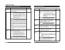
When connecting
● Tu rn OFF the power supply to all equipment to be used before making connections.
● Carefully read the Instructions for each piece of equipment to be used before making
connections.
● For the appropriate connection cables and the length of these, carefully read “Connections
on the back” on page 16.
● The control signal cable cannot be used for loop connection.
Set to M.DROP
Set to M.DROP when the RM-P2580 is used
as a remote control unit. When controlling
from another machine, make sure that it
matches the communication system used.
MMCO UNICATION
ST LE M.DROPY
MA H NE DII 1C