


E-14
CONNECTION/INSTALLATION
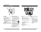
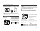
SET
MENU
CAMERA
SETUP
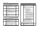
EXT TERM-OFF
INT/GL
DUPLEX
RX TERM-OFF
IOT USED
ON
LL
SIMPLEX
ON
VIDEO
DC
DC12V
AC24V
CLASS 2 ONLY(U TYPE)
ISOLATED POWER ONLY
(E TYPE)
TX
+
TX
-
RX
+
RX
-
AUX
Y/C OUT
SYNC IN
POWER
VIDEO OUT
GND
A
B
CD
SEE INST-
RUCTION
MANUAL
1
+
-
2
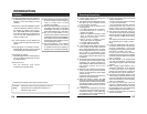
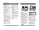
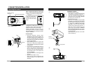
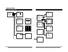
Execute connection/installation according to the procedures described below.
Turn OFF the power supply to all equipment to be used before making carefully.
1.
Mounting the lens
(੬ Page 15)
4.
Setting the switches
(੬ Page 13)
6.
Back focus adjustment
(੬ Page 21)
5.
Lens adjustment
(੬ Page 20)
7.
Auto white balance
control adjustment
(੬ Page 22)
3.
Mounting the camera
(੬ Page 18)
To controlling systems
such as RM-P2580
To alarm terminals
such as switches
Monitor
2.
Connections
(੬ Page 16)
DC 12V/AC 24V
power supply
Genlock sync
signal generator
Procedures
This is the connected example of the TK-C1430E.
TK-C1431EG ੬ Page 17
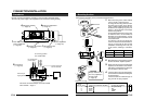
E-15
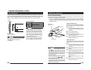
Mounting the lens
VIDEO
DC
IRIS
VIDEO
DC
3
42
1
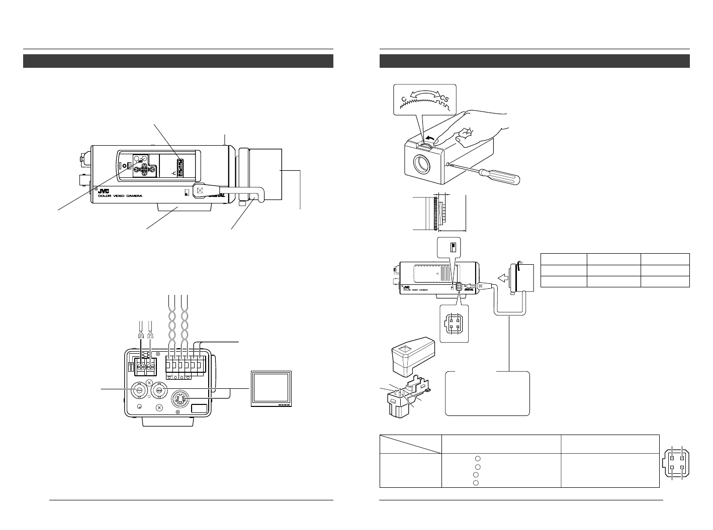
Mount the lens according to the procedures described below.
1.
Before mounting a lens, check whether
it is a C-mount or CS-mount lens.
To change the mounting method, loosen
the back-focus locking screw (M 2.6)
using a Phillips head screwdriver, turn
the back-focus adjusting ring with your
fingers or the screwdriver and change
the mounting method.
As regards the dimension (b) of the area
to which the lens is to be installed as
illustrated on the left diagram, use the
one with less value than what’s shown
in the table below.
For both the C-mount and CS-mount,
never use whatever exceeds the dimen-
sion (b), as such will not allow normal
installation and damage the inner part
of the camera, resulting in a malfunc-
tion.
The F mark indicates a focal point.
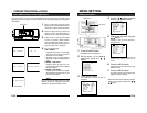
2.
Mount the lens on the camera by turning
the lens clockwise. Adjust its position.
3.
When using an auto-iris lens with an EE
amplifier, turn the switch to the “VIDEO”
side. When no EE amplifier is equipped,
turn the switch to the “DC” side.
4.
If the lens has an auto-iris mechanism,
connect the lens cable after checking the
pin arrangement.
If the lens cable has a different type of
plug, use the 4-P plug supplied.
Lens Flange back (c) Dimension (b)
C mount lens 17.526mm 5.5mm or less
CS mount lens
12.5mm 5.5mm or less
1
3
4
2
B
F
L
O
C
K
(b)
(c)
F
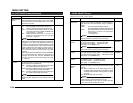
Lens DC IRIS VIDEO IRIS
Pin No. (does not contain EE amplifier) (contain EE amplifier)
1 Brake
–
9V [max 50mA]
2 Brake
+
NC
3Drive
+
VIDEO
4Drive
–
GND
3.
2.
4.
Attached 4 pin plugs
1
3
2
4
CAUTION:
Always attach the fer-
rite core (supplied) to
the lens cable.
(੬ Page 16)