


24
Setup
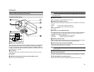
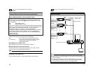
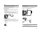
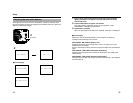
Connecting alarm input/output terminal
Ⅵ Alarm input terminal
Connect infrared sensor, door sensor, metal sensor or sensor of manual
switch and the like.
● To prevent noise from entering the internal circuit, supply non-voltage
setting signal.
● Do not supply voltage.
● Can be set via menu whether to set to alarm when the contact is short
(MAKE), or when the contact is open (BREAK). (A Pg. 39)
● Supply such that the alarm signal continues for more than 200 ms. The
recognition of alarm signal may not be guaranteed if less than 200 ms.
Ⅵ Alarm output terminal
Connect to alarm devices such as alarm, indicator, light or buzzer.
● As it is an open type collector output insulated by photocoupler, it will turn
on during alarm.
● This terminal has polarity. Make sure to connect such as the voltage of +
terminal is higher than - terminal. It will be damaged if reverse voltage is
supplied.
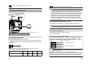
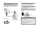
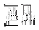
Connecting the back panel (continued)
CLASS 2 ONLY(U TYPE)
ISOLATED POWER ONLY(ETYPE)
SEE INSTRUCTION
MANUAL
POWER
VIDEO OUT
SELECTOR
SET
MENU
INT LL
ONRX TERM-OFF
+
1
2
DC12V d
AC24V H
IN
GND
OUT +
OUT -
22ǡ
25
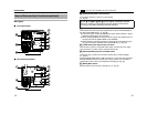
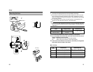
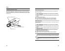
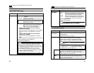
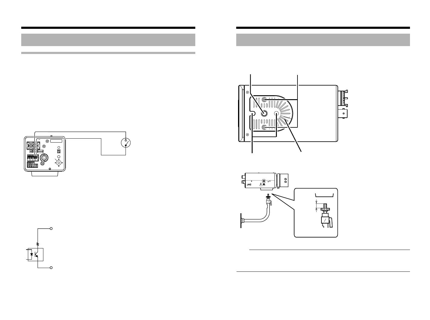
When mounting the camera on a fixer, pan/tilt and the like, use the camera-
mounting screw hole located on the camera-mounting bracket.
Note:
● Use a camera-mounting screw with a length shorter than 7 mm from the
camera-mounting face. Do not use a screw that is longer than the specified
length. It may damage the internal parts.
Mounting the camera
IRIS
VIDEO
DC
LEVEL
COLORVIDEOCAMERA
Camera-mounting
screw hole
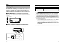
Camera-mounting bracket fixing
screws (x2: M2.6 x 6 mm)
Rotation-preventive hole Camera-mounting bracket
7 mm
or
less