


14
Introduction
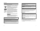
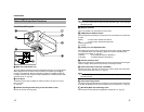
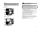
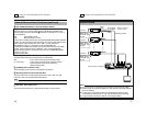
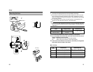
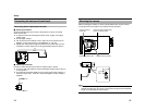
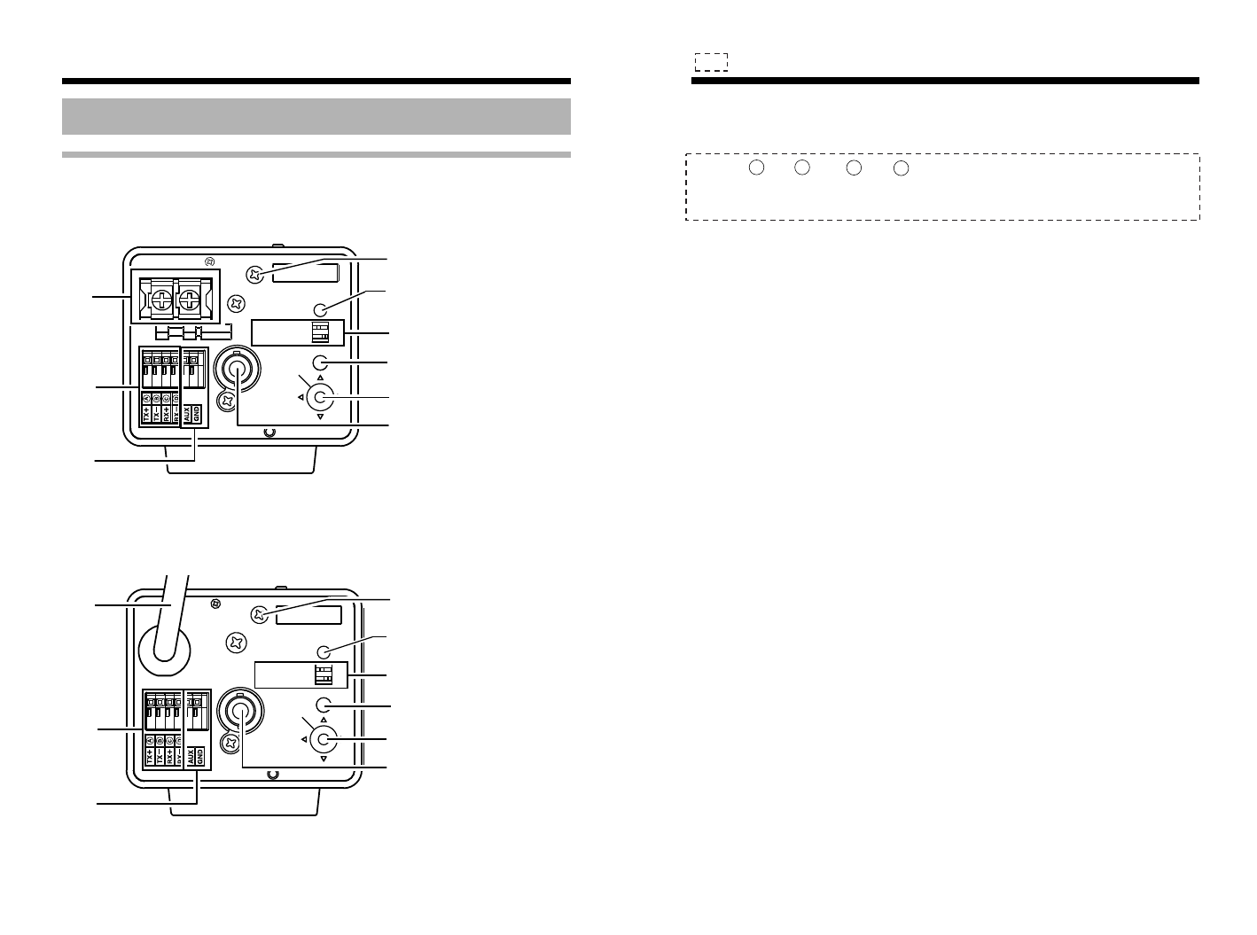
Back panel
Name of Parts and their Functions (continued)
CLASS 2 ONLY(U TYPE)
ISOLATED POWER ONLY(E TYPE)
SEE INSTRUCTION
MANUAL
POWER
VIDEO OUT
SELECTOR
SET
MENU
INT LL
ONRX TERM-OFF
+
1
2
DC12V d
AC24V H
SEE INSTRUCTION
MANUAL
POWER
VIDEO OUT
SELECTOR
SET
MENU
INT LL
ONRX TERM-OFF
K
L
T
L
M
M
N
R
Q
P
R
Q
P
S
S
O
N
O
Ⅵ TK-C1530/TK-C925
Ⅵ TK-C1531EG/TK-C926EG
15
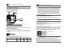
K [AC24V,DC12V] Power input terminal
To connect to AC 24 V or DC 12 V power supply.
(A Pg. 22)
L [TX+ ,TX- ,RX+ ,RX- ] Control signal connection terminal
Terminal for inputting or outputting signals with electrical characteristics
conforming to the EIATIA RS-422A or RS-485 standard.
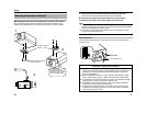
M [AUX,GND] External terminal
This terminal is for the input/output signals that are set in the AUX MODE of
the AUX FUNCTION screen. (A Pg. 38)
● This terminal also outputs the B&W/Color signal. [Open-collector L signal.
Maximum voltage 25 V, current 30 mA]
● When switching B&W/Color using the control signal, the signals are input
through this terminal. [B&W: MAKE, Color: BREAK]
● When switching scene files using the control signal, the signals are input
through this terminal. (SCENE A and SCENE B only) (A Pg. 64)
N [VIDEO OUT] Video signal output connector
This connector outputs a composite video signal. Connect this to the video
input connector of a video monitor, switcher and the like.
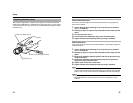
O [SELECTOR/SET] Selector switch/Set button
This allows user to select menu screens and change or confirm settings.
(A Pg. 34)
Press the SELECTOR switch up (J) and hold for 1 second to set to [FOCUS
ADJUST MODE] and open the lens iris for easy focusing. (As the depth of
object field is lower, focus can be adjusted accurately.)(A Pg. 28)
P [MENU] Menu button
When pressed, a menu screen is brought up. (A Pg. 34)
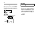
A
B
C
D
: Only for TK-C1530U/E and TK-C1531EG