16
Introduction
Q
[RX TERM-OFF,ON/INT,LL] Function Selector Switch
ⅷ [RX TERM-OFF,ON] RX Signal Terminal ON/OFF Switch
This sets whether or not the signal between RX+ and RX- from the
control signal connection terminals L should be terminated at the value of
110K resistance.
ON : Terminated at 110K.
OFF : Not terminated at 110K.
If the system including the camera is the MULTIDROP (Multi DROP, RS-485)
system, only the last camera mounted along the control signal cable is set to
AONB and the other cameras are set to AOFFB. (In the case of the
MULTIDROP system, it is necessary to set the MACHINE ID.)
If the system including the camera is the P TO P (Point to Point, RS-422A)
system, set this switch of all the cameras to AONB. To switch between
communication systems, use the item STYLE on the COMMUNICATION
screen. (A Pg. 51)
(Default setting: ON)
ⅷ [NT,LL] Selector Switch for Synchronizing System
This switch sets the synchronizing system for the camera.
INT : This is set for internal synchronization (INT).
LL (Line Lock) : This is set to synchronize the camera’s vertical
synchronization to the power frequency.
(Default setting: INT)
R [POWER] Power indicator lamp
This lamp lights up when power is supplied to the camera.
S Mounting Screw for Fall Prevention Wire
Use this screw when mounting the fall prevention wire to this unit. (Fall
prevention wire is not supplied with this product.)
Note:
● Connect the fall prevention wire to prevent this unit from falling accidentally.
T AC 220 V-240 V power cord
This connects the camera to a commercial AC 220 V-240 V socket.
Name of Parts and their Functions (continued)
C D
: Only for TK-C1530U/E and TK-C1531EG
17
Setup
Memo:
● Turn off the power of devices to be used before connecting the cables.
● Read through the “Instruction Manual” of the devices to be used carefully
before connecting.
● For the types of connecting cables and the distances required, read
AConnecting the back panelB (A Pg.22) carefully before connecting.
● Loop connection cannot be made for control signal cables.
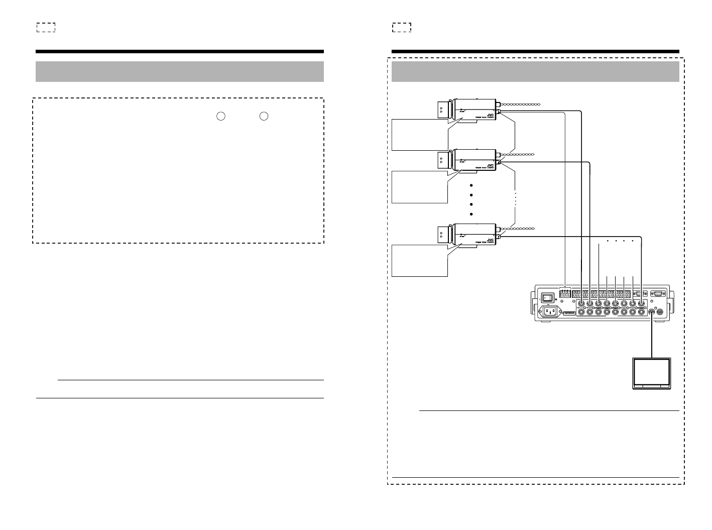
System Example
1
TOCAMERA DATAI/O
RX
+
RX
-
TX
+
TX
-
COM
1 2 3 456 7 8
COM
9/110/211/312/413/514/615/716/8
COM COM COM
CAMERA
SW
UNIT
ALARM
AUTO
4312 8756
2 3 4 5 6 7
8
1
MONITOR
OUTPUT
MONITOR
SERIAL-2SERIAL-1
VIDEOINPUT
VIDEOOUTPUT
OUTPUT
2
1
ON
2 3 4 5 6 7
8
DIGITAL
ALC
LEVEL
AvPk
LH
DIGITAL
ALC
LEVEL
AvPk
LH
DIGITAL
ALC
LEVEL
AvPk
LH
Camera 1
Camera 2
Camera 8
Control Signal
Cable
Power
Cable
TK-C1530U/E : AC24 V or DC12 V
TK-C1531EG : AC220 V-240V
Video Signal Cable
Remote control unit and etc
Monitor
MACHINE ID : 1
(MENU screen)
RX TERM : OFF
(Switch)
MACHINE ID : 2
(MENU screen)
RX TERM : OFF
(Switch)
MACHINE ID : 8
(MENU screen)
RX TERM : ON
(Switch)
: Only for TK-C1530U/E and TK-C1531EG


