


E-12
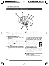
REC
PLAY
FFREW
REVERSE
PAUSE/
STILL
REC
CHECK
STOP/EJECT
COUNT/
CLOCK
TIME
MODE
TIMER
REC
AL/PL
RESET
MENU
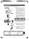
VIDEO CASSETTE RECORDER
SHIFT/TRACKING
SET/V.LOCK
RESET
/CANCEL
OPERATE
SR-L910
OPE. LOCK
1
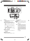
TO CAMERA
TO CAMERA
DATA I / O
DATA I / O
RX
RX
+
RX
RX
-
TX
TX
+
TX
TX
-
COM
COM
12 3456 78
COM
COM
9/1
9/1
10/2
10/2
11/3
11/3
12/4
12/4
13/5
13/5
14/6
14/6
15/7
15/7
16/8
16/8
COM
COM
COM
COM
COM
COM
CAMERA
CAMERA
SW
SW
UNIT
UNIT
ALARM
ALARM
AUTO
AUTO
4312 8756
2 3 4 5 6 7
8
1
MONITOR
MONITOR
OUTPUT
MONITOR
MONITOR
SERIAL-2
SERIAL-2
SERIAL-1
SERIAL-1
VIDEO INPUT
VIDEO OUTPUT
OUTPUT
OUTPUT
2
1
ON
ON
2 3 4 5 6 7
8
POWER
OFF
AC INPUT
ALC
LEVEL
Av Pk
L H
ALC
LEVEL
Av Pk
L H
ALC
LEVEL
Av Pk
L H
•••••
CAMERA
SW
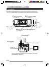
Remote Control Unit
RM-P2580
Time lapse VCR
MONITOR
MONITOR
CAM SW
OUT
VIDEO IN
COM
TO
CAMERA
MONITOR
OUTPUT 2
MONITOR
OUTPUT 1
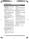
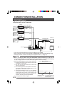
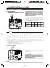
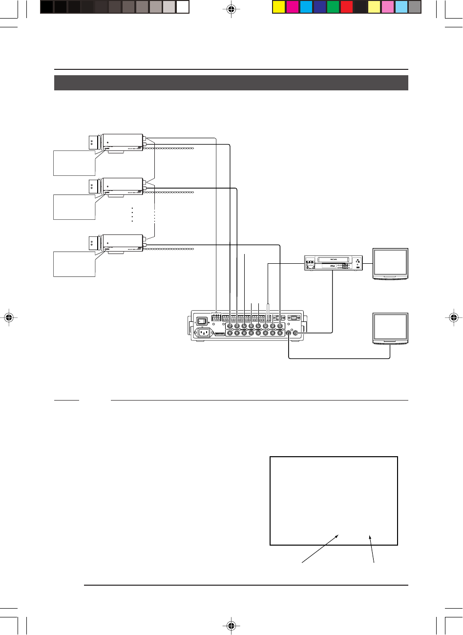
CONNECTION/INSTALLATION
RM-P2580 System
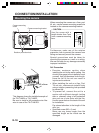
Ⅲ System with up to 8 cameras
Camera
TK-C1480
Camera
TK-C1480
Camera
TK-C1480
Camera 1
Camera 2
Camera 8
Control signal cable
Video signal cable
Power
cable
AC24V
or
DC12V
AC24V
or
DC12V
AC24V
or
DC12V
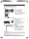
MONITOR screen
(example showing camera ID as “05”)
This is the connected example of the TK-C1480U or TK-C1480E.
When controlling with any system except the RM-P2580, execute proper settings using
switches and menu screens according to the systems used. (੬ Page 14)
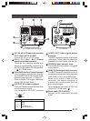
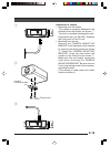
PROT OOLDUPLEXID-05C :
“DUPLEX” should
be displayed.
The number shown in the
□□ part of ID-□□
should be correct.
MACHINE ID:1
(Menu screen)
RX TERM: OFF
(switch)
MACHINE ID:2
(Menu screen)
RX TERM: OFF
(switch)
MACHINE ID:8
(Menu screen)
RX TERM: ON
(switch)
MEMO
• When operating a system using the RM-P2580, several cameras (up to 8) can be
connected and used on one control signal cable. Consequently, an incorrect switch setting
on just a single camera will cause the entire system to work incorrectly.
• Confirm switch settings on the screen as follows.
q Confirm that the image from the camera to be checked
is displayed on the monitor.
w Turn OFF and then ON the AC 24 V power to the
camera to be checked.
e The camera begins the initial operation and charac-
ters similar to those shown in the illustration on the
right appear on the monitor screen.
r Confirm that “DUPLEX” and “ID-□□” are displayed
and that the ID number is the correct number (the
number should be the same as the number of the
VIDEO INPUT terminal to which the camera is con-
nected on the rear panel of the RM-P2580).
t If wrong, set the camera ID again.