


E-18
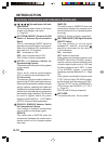
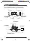
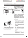
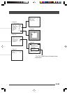
DC12V
AC24V
CLASS 2 ONLY(U TYPE)
ISOLATED POWER ONLY
(E TYPE)
T
X
+
T
X
-
R
X
+
R
X
-
A
U
X
Y/C OUT
SYNC IN
POWER
VIDEO OUT
G
N
D
A
B
CD
SEE INST-
RUCTION
MANUAL
+
-
1
2
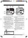
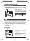
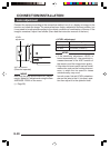
2mm
6mm
M3 x 6mm
MAX.
7mm
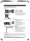
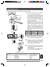
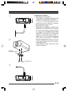
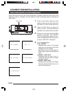
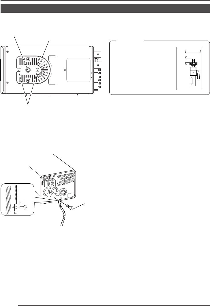
Mounting the camera
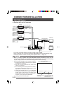
CONNECTION/INSTALLATION
Camera mounting
screw
Camera-mounting bracket
Rotation prevention hole
When mounting the camera on a fixer, pan/
tilt, etc., use the camera mounting screw hole
located on the camera-mounting bracket.
Furthermore, make use of the rotation
prevention hole to prevent the camera from
falling and securely mount the camera.
Special precautions must be taken for
mounting the camera on a wall or a ceiling.
We are not liable for any damage caused by
improper installation.
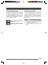
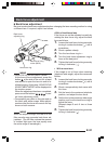
Fall Prevention
• Exercise maximum caution when
installing the unit to the wall or ceiling. You
should not engage in the installation work
yourself. Ask a professional to do the job,
since the fall of the unit can result in
injuries and accidents.
• When installing the unit on a fixer, Pan/
Tilt unit, etc., make sure to install it firmly
using a rotation-preventing hole provided
to prevent fall.
• To prevent fall, connect the unit to a
section with sufficient strength (ceiling
slab or channel) using a fall prevention
wire such as a wire chain and the like.
Use the screw hole on the back of the unit
for installation.
Pay utmost attention to the length of the
wire, too.
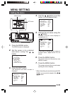
• Specified screw (M3 × 6 mm)
Never use any screw longer than the
specified length as the inside can be
damaged.
CAUTION:
Use the screw with a
length shorter than 7mm
from a camera-mounting
face.
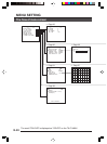
This diagram shows the installed example of
the TK-C1480U or TK-C1480E.
Be sure to install a fall preventive wire like-
wise in case of the TK-C1481EG.