


E-13
CAMERA
SETUP
SET
MENU
EXT TERM-OFF
INT/GL
DUPLEX
RX TERM-OFF
NOT USED
ON
LL
SIMPLEX
ON
EXT TERM-OFF
INT/GL
DUPLEX
RX TERM-OFF
NOT USED
ON
LL
SIMPLEX
ON
VIDEO
DC
IRIS
AWC
A RX
+
B RX
C TX
+
D TX
TX
+
A
TX
B
RX
+
C
RX
D
TX
+
A
TX
B
RX
+
C
RX
D
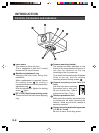
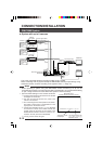
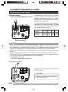
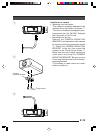
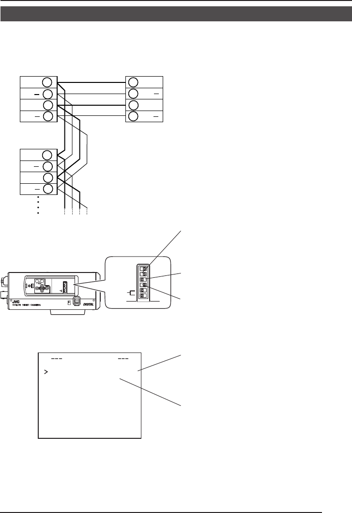
RM-P2580
Camera 2
control signal
connection terminals
Connect:
Camera TX+ to RM-P2580 RX+
Camera TX– to RM-P2580 RX–
Camera RX+ to RM-P2580 TX+
Camera RX– to RM-P2580 TX–
The A B C D marks indicated on both the
camera terminals and the RM-P2580 termi-
nals facilitate correct connections. Connect
the terminals with identical marks.
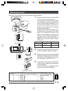
Ⅲ Connecting the control signal cable
(Use a twisted-pair cable for connection. ੬ Page 17.)
Camera 1
control signal
connection terminals
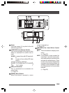
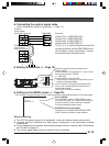
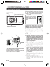
Ⅲ Setting the switches (੬ Page 10)
Select the synchronization method of the
camera image.
Set the switch on all cameras to LL (Line Lock)
and match with the V. PHASE.
(੬ Page 26.)
Set this switch to the DUPLEX
* If the setting is changed, be absolutely sure to
switch on the power again.
Set this switch to ON (signal termination ON)
only on the camera placed at the end of the
control signal cable.
Set to OFF on all other cameras.
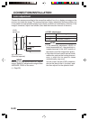
Ⅲ Setting on the MENU screen (੬ Page 33)
* If the setting is changed, escape from the menu screen once, and definitely switch on the power again.
MACHINE ID setting switches
Set this item to match the RM-P2580 VIDEO
INPUT terminal number for each camera.
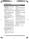
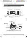
When connecting
● Turn OFF the power supply to all equipment to be used before making connections.
● Carefully read the Instructions for each piece of equipment to be used before making
connections.
● For the appropriate connection cables and the length of these, carefully read “Connections
on the back” on page 16.
● The control signal cable cannot be used for loop connection.
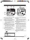
Set to M.DROP
Set to M.DROP when the RM-P2580 is used
as a remote control unit. When controlling from
another machine, make sure that it matches
the communication system used.
MMCO UNICATION
ST LE M.DROPY
MA H NE DII 1C