


16
Installation and connection
NOTE:
●Turn OFF the power supply to all equipment to
be used before making connections.
●Read the Instruction Manual for each piece of
equipment to be used before making
connections.
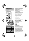
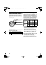
NOTE:
●Power consumption of TK-C215V4/TK-
C215V12 are different from one another.
When installing a mixture of these models,
select a cable length according to the power
consumption of each model. Alternatively,
install based on the model with the highest
power consumption.
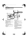
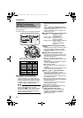
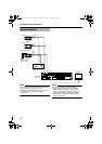
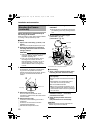
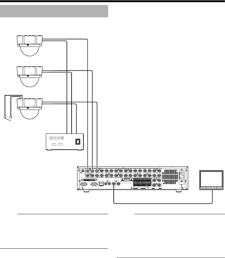
System diagram
COM
EXTREC
OUT
REC
SER
IN
OUT
RST
CLK
OUT
WAR
INCOMRST
OUT
161412108642
15131197531
ALARM
1316912
5
814/ 16
EEOUT
ACIN
SCSI
RS-232C UPS
21
AUDIOOUT VIDEOOUT
21
LAN
AUDIOIN
VIDEOIN
THRUOUT
12345678910111213141516
SIGNALGND
CAUTION
RISK OF ELECTRIC SHOCK
DO NOT OPEN
AVIS:RISQUEDECHOC
ELECTRIQ
(220V–240V )
TK-C215V4
Video signal
Power
Power
Video
signal
Power
Video
signal
Power Unit
DC 12 V or AC 24 V
VIDEO IN
MONITOR
VIDEO OUT
Digital Video
Recorder etc.
TK-C215V4
TK-C215V12
Alarm signal
METAL CONTACT
TK-C215V4_V12_EN.book Page 16 Wednesday, August 2, 2006 1:18 PM