


19
Ⅵ Connecting
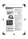
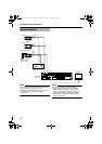
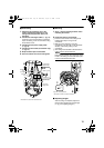
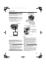
1. Attach the fall prevention wire to the
camera, followed by attaching it to the
ceiling slab (Fall prevention wire is not
included.)
2.
Connect the video signal cable. (
A
pg. 14)
Lower the cover and connect the connectors.
Upon connecting, cover the connectors using
the protection cover.
3.
Connect the input power supply cable.
(
A
pg. 16)
4.
Connect the alarm cable.(TK-C215V12 only)
(A pg. 15)
5.
Wrap insulation tape around cables.
6.
Insert the camera unit into the ceiling hole.
Ⅵ Mounting
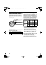
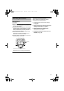
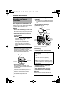
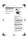
1. Align j with the shooting direction when
mounting the camera.
2.
Fasten the camera. (x3 locations)
A Press the screw head of the ceiling mount
bracket all the way in using a cross
screwdriver.
B With the screw pressed in using the
screwdriver, turn about 90 Њ in the clockwise
direction, followed by pulling out the
screwdriver.
C The ceiling mount bracket is attached to the
ceiling and the camera fastened.
NOTE:
Dismantle the camera upon turning the screw
heads of the ceiling mount bracket (x3) by 90 Њ
in the counterclockwise direction.
Ⅵ Adjusting Images
After mounting is completed, adjust the
images while checking the actual image.
(A pg. 23 AAdjusting ImagesB)
1.
6.
2.
5.
3.4.
Protection
cover
Solder or crimp
Insulation tape
Wrap with tape
Input power
supply cable
Fall prevention
wire
(not supplied)
*TK-C215V12 is used in the above illustration.
Alarm signal cable
(TK-C215V12 only)
B
A
1.
2.
F
RONT
U
P
Align with shooting direction
*TK-C215V4 is used in the above illustration.
TK-C215V4_V12_EN.book Page 19 Wednesday, August 2, 2006 1:18 PM