


18
Installation and connection
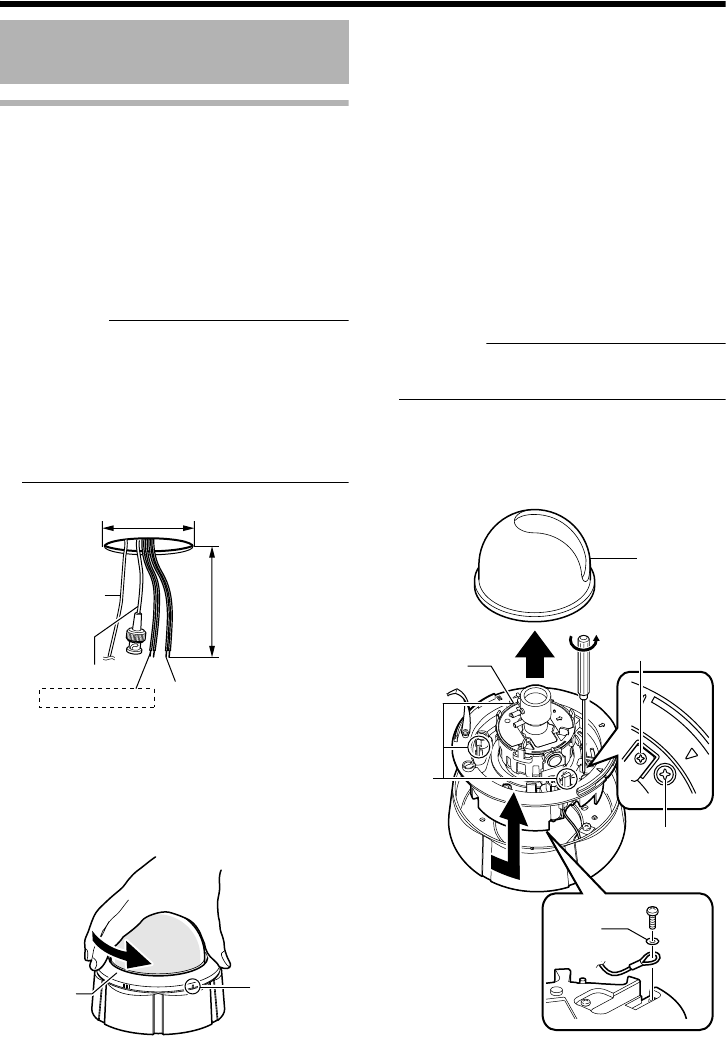
Embedding the camera to the ceiling
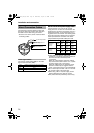
* Make use of a ceiling material with a thickness
between 9.5 mm to 22 mm.
Ⅵ Setup
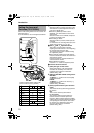
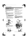
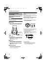
1. Open a hole in the ceiling. (R120 mm, 4 3/4
inches)
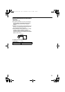
2.
Draw the fall prevention wire mounted to
the ceiling slab and the cable out from the
ceiling in advance.
CAUTION:
● Select a suitable fall prevention wire based
on length, strength, location, material
(insulation property), etc.
●
Use a ring on the fall prevention wire for
mounting to the camera unit with an
internal diameter of at least
R
3.1 mm or and
not larger than
R
5.5 mm, and an external
diameter that is not larger than
R
9 mm.
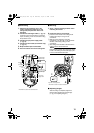
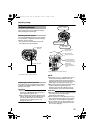
3.
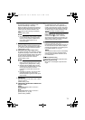
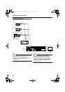
Remove the dome cover.
As illustrated in the diagram, hold the dome
ring such that the position mark comes
between the thumb and index finger. Turn the
ring in the counterclockwise direction to
remove.
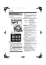
4.
Remove the inner dome
The inner dome is secured with claws
(3 locations). Hold the inner dome and remove
it from the claws.
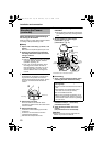
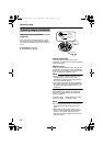
5.
Remove the outer case.
(This method does not require an outer case.)
A Loosen the camera fastening screw with a
screwdriver
B To remove, turn the camera unit in the
counterclockwise direction
6.
Dismantle the supplied fall prevention wire
Unfasten the mounting screw for the fall
prevention wire at the rear of the camera unit
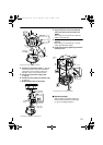
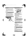
7.
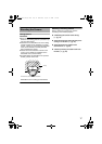
Loosen the pan fastening screw.
CAUTION:
Moving the lens unit without loosening the pan
fastening screw may damage the lens unit.
8.
Set the switches for video images.
(TK-C215V4A pg. 10)
(TK-C215V12A pg. 12)
Mounting the Camera
(continued)
1.
2.
R120 mm
(4 3/4 inches)
Approx. 100 mm
(3 7/8 inches)
Video signal cable
Fall prevention
wire
(not supplied)
Power supply cable
Alarm signal cable
*TK-C215V12 only
3.
Dome Ring
Position mark
B
A
5.
7.
6.
5.
4.
Camera
Fastening Screw
Pan Fastening
Screw
Washer
Inner Dome
Claws
(3 locations)
*TK-C215V4 is used in the above illustration.
TK-C215V4_V12_EN.book Page 18 Wednesday, August 2, 2006 1:18 PM