


21
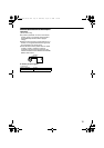
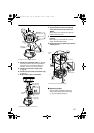
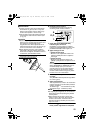
4.
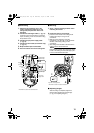
Connect the video signal cable. (
A
pg. 14)
Lower the protection cover and connect the
connectors. Upon connecting, restore the
protection cover to cover the connectors.
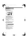
5.
Connect the input power supply cable.
(
A
pg. 16)
6.
Connect the alarm cable.(TK-C215V12 only)
(A pg. 15)
7.
Wrap insulation tape around cables.
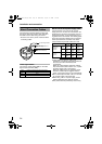
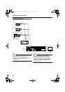
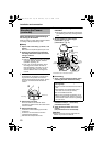
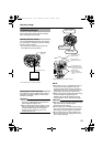
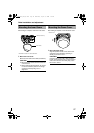
Ⅵ Mounting
1. Align the position mark of the fastened
outer case with that of the camera unit.
NOTE:
When doing so, be careful not to catch the
cables in the outer case.
2.
Turn the camera unit in the clockwise
direction.
T When doing so, ensure that the X mark is
visible. (See illustration below)
3.
Fasten the camera by tightening the camera
fastening screw.
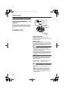
Ⅵ Adjusting Images
After mounting is completed, adjust the
images while checking the actual image.
(A pg. 23 AAdjusting ImagesB)
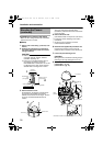
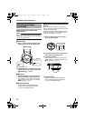
3.
2.
1.
F
RON
T
UP
Be sure to loosen
the screw.
Attach from
the ceiling
slab
Fall prevention
wire
(not supplied)
Outer case
mounting screws
Less than 4 mm
TK-C215V4 is used in the above illustration.
4.
7.
5.6.
Protection
cover
Solder or crimp
Insulation tape
Wrap with tape
Input power
supply cable
*TK-C215V12 is used in the above illustration
Alarm signal cable
(TK-C215V12 only)
3.
2.
1.
Position
mark
Camera
fastening screw
T Check
*TK-C215V4 is used in the above illustration.
TK-C215V4_V12_EN.book Page 21 Wednesday, August 2, 2006 1:18 PM