


10
1
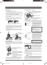
TO CAMERA
TO CAMERA
DATA I / O
DATA I / O
RX
RX
+
RX
RX
-
TX
TX
+
TX
TX
-
COM
COM
1 2 3 4 5 6 7 8
COM
COM
9/110/2
10/2
11/312/4
12/4
13/5
13/5
14/6
14/6
15/716/8
16/8
COM
COM
COM
COM
COM
COM
CAMERA
CAMERA
SW
SW
UNIT
UNIT
ALARM
ALARM
AUTO
AUTO
431 2 875 6
2 3 4 5 6 7
8
1
MONITOR
MONITOR
OUTPUT
OUTPUT
MONITOR
MONITOR
SERIAL-2SERIAL-1
VIDEO INPUT
VIDEO INPUT
VIDEO OUTPUT
VIDEO OUTPUT
OUTPUT
OUTPUT
2
1
ON
ON
2 3 4 5 6 7
8
POWER
OFF
ON
AC INPUT
MONITOR
OUTPUT 1
TO
CAMERA
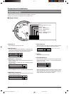
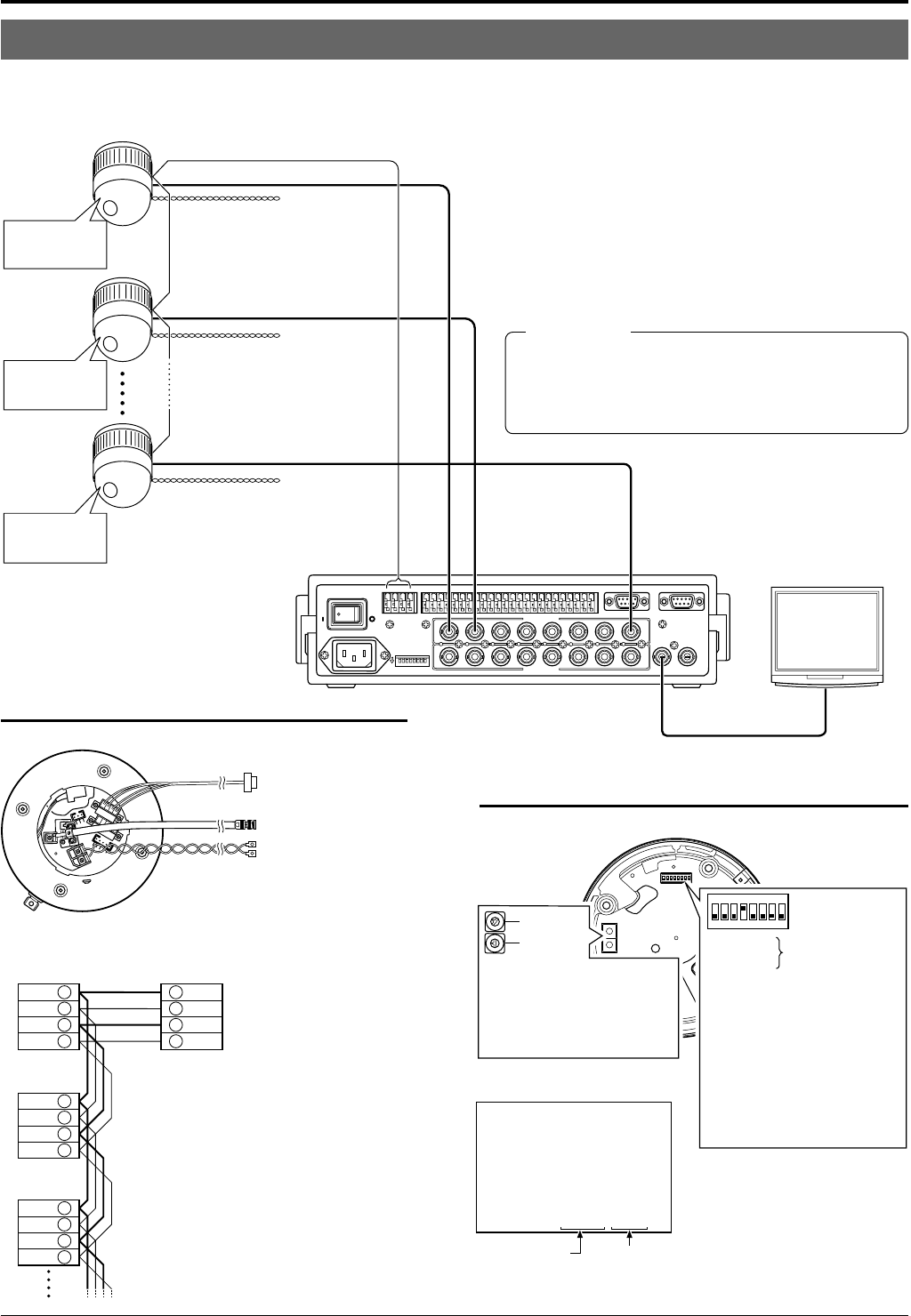
Remote control unit
RM-P2580
Control signal cable
Coaxial cable
AC 24 V
power supply
(
CAUTION
AC 24 V
power supply
(
CAUTION
AC 24 V
power supply
(
CAUTION
Monitor
Camera 1
Camera 2
Camera 8
TK-C655/
TK-C676
TK-C655/
TK-C676
TK-C655/
TK-C676
MACHINE ID: 01
Switch 8: OFF
(RX TERM)
MACHINE ID: 02
Switch 8: OFF
(RX TERM)
MACHINE ID: 08
Switch 8: ON
(RX TERM)
TX
+
A
TX
–
B
RX
+
C
RX
–
D
TX
+
Camera 1
CONTROL terminals
Camera 2
CONTROL
terminals
Camera 3
CONTROL
terminals
RX
+
A
RX
–
B
TX
+
C
TX
–
D
RM-P2580
terminal
A
TX
–
B
RX
+
C
RX
–
D
TX
+
A
TX
–
B
RX
+
C
RX
–
D
Connection of the control signal cable
(A twisted pair cable is recommended.)
Power cable
Control signal cable
To AC 24V power supply
(
CAUTION
To the TO CAMERA connector of the
RM-P2580 and to the next camera
Coaxial cable
To the CAMERA INPUT connector
of the RM-P2580
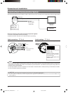
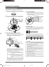
Duplex display ID No. display
LPROCESS<<>>I INTIA
:--I--PAN
:--I--TILT
DUPLEX ID-01ROT>P COOL
Camera 1 monitor display
at power ON
(ID check procedure
☞
P. 15)
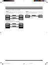
Switch 1
:
Switch 2
:
Switch 4 : ON
Switch 5 : OFF
Switch 7 : Invalid (Set to OFF)
Switch 8 :
Figure of 1
Figure of 10
Set it to the same number as the
VIDEO INPUT terminal of the RM-
P2580.
(Example) Camera 1:
Set the figure of 10 to “0” and
figure of 1 to “1”.
Set to ON only for the
camera connected at
the end of the control
signal cable.
Set to OFF for all
other cameras.
Machine ID
0
9
8
7
6
5
4
3
2
1
0
9
8
7
6
5
4
3
2
1
1
2
3
4
6
7
8
5
O
F
F
Invalid (Set to OFF.)
A Multi-Drop Communication System
Ⅵ A system that employs the RM-P2580 as the controller
The following figure shows a system that can accommodate up to eight cameras. (100 positions can be preset per camera.)
Observe the following points when connecting compo-
nents together:
•Turn all the components off before proceeding.
• Read the instruction manuals of all components before pro-
ceeding.
•For the types and lengths of connection cables, see “Cable
Connections” on page 16.
• Do not connect the control signal cables in a loop.
Cable connections
☞
P. 16
(Terminal side of Ceiling Mount)
Switch settings
☞
P. 14
(Setting switches are on the side of the Ceiling Mount)
Each terminal on the camera and the RM-
P2580 is marked A
⅜
, B
⅜
, C
⅜
or D
⅜
. In order
to facilitate understanding and to avoid
connection mistakes, it is recommended
to connect the terminals carrying the
same marks.
CAUTIONS
● The AC 24 V power supply must be isolated from the pri-
mary line. (ISOLATED POWER ONLY)
● In order to prevent an excessive current flow through the
power supply wire or camera due to a short circuit, a fuse
must be installed in the power supply line.
Connections & Installation
TK-C676-C655 in_LWT0200-001A-H 04.6.23, 3:38 PM10