


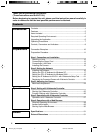
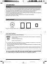
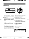
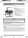
9
(Side and rear views)
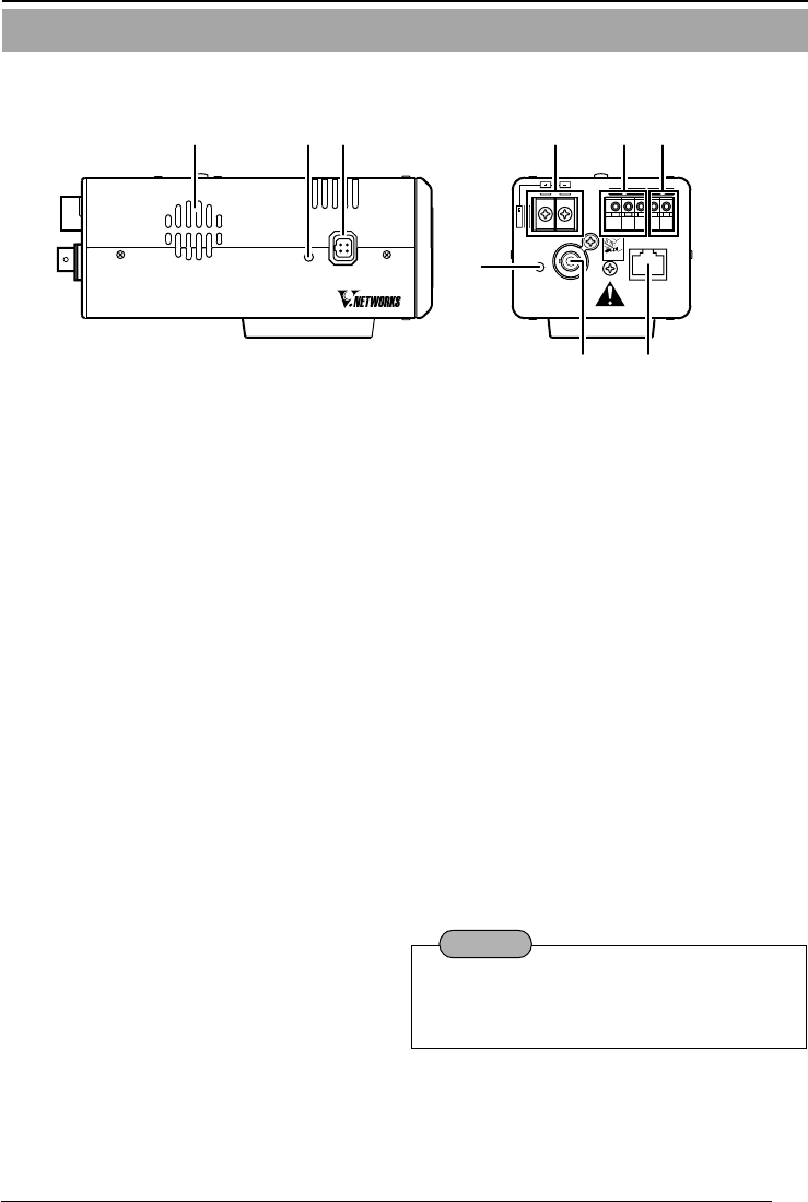
Controls, Connectors and Indicators (continued)
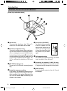
9 Ventilation opening
For the internal cooling fan. Install the cam-
era in a way that does not cover the opening.
0 [RESET] button
Press this button to reset VN-C11. If this but-
ton is held down for 2 seconds or longer, the
values set with [V.Networks Setup Tool] re-
turn to those set at the factory, and VN-C11
restarts.
! [IRIS] terminal
For connecting with a DC IRIS lens.
(A video iris lens cannot be connected.)
@ [POWER] indicator
This indicator starts blinking when the power
is turned on. When the camera is ready for
network connection, this becomes steady on.
If the indicator blinks while the camera is in
use, check the camera and/or the network
equipment.
# [DC 12 V/AC 24 V] Power terminal
For connecting to a DC 12 V or AC 24 V, 50 Hz/
60 Hz, power source. (
☞ Page 13)
$ [ALARM INPUT] terminals
For connecting with an external alarm equip-
ment.
% [ALARM OUTPUT] terminals
For connecting with an external alarm equip-
ment.
^ [10 BASE-T/100 BASE-TX]
For network connection with a LAN cable.
(
☞ Page 14)
& [MONITOR OUT] terminal
For connecting to monitor TV when deciding
camera angles.
RESET
IRIS
0
9
!
CLASS
2
ONLY
For
USA
ISOLATED
POWER
ONLY
For EUROPE
POWER MONITOR OUT
10BASE-T/100BASE-TX
For USA
DO NOT CONNECT TO THE
TELEPHONE NETWORK
G
2
21
1
OUT COM
ALARM
DC12V
AC24V
OUTPUT
INPUT
PUSH
#
@
$ %
^&
For angle adjustment only, problems such
as noise may occur if connected with a
switcher.
Caution
VN-C10_E_01-24.pm6e 03.4.24, 10:02 AM9