


95
6
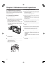
Chapter 6 Maintenance and inspections (continued)
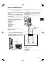
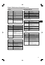
Matsushita part number K1AB120H0001
Maker part number HR12-14RA-20SC
(Hirose Denki)
1
2
3
4
5
6
7
8
9
10
11
12
13
14 15
16
17
18
19 20
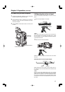
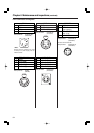
Maker part number
HR10A-10R-10SC (71)
(Hirose Denki)
Connector at the cable side
Maker part number
HR10A-10P-10P(73)
(Hirose Denki)
1
2
4
5
6
7
8
910
3
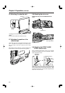
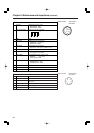
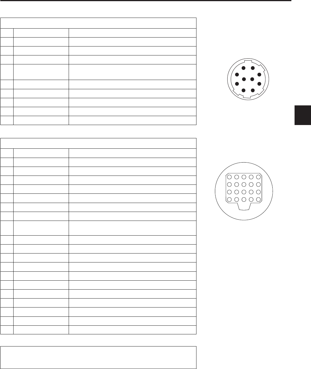
REMOTE
1 CAM DATA (H) Data from the camera to the remote control (H)
2 CAM DATA (C) Data from the camera to the remote control (C)
4 CAM CONT (C)
Control signals from the remote control to the camera (C)
5 RC-ON Identification signals of the remote control
Low: ON
6 RC VIDEO OUT Video signals output to the remote control
7 RC VIDEO GND GND of the video signals to the remote control
8 NC Not used
9 UNREG 12V DC +12 V power supply (AJ-RC10G: Max. 0.75 A)
10 GND GND
3 CAM CONT (H)
Control signals from the remote control to the camera (H)
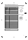
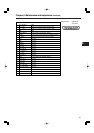
VF
1 UNREG-12V DC +12 V power supply (AJ-HVF21G: About 0.35 A)
2 UNREG-12V DC +12 V power supply
4 VF-PB-GND GND for the viewfinder PB signals
5 VF-PR-GND GND for the viewfinder PR signals
6 VF-Y Viewfinder Y signals output
7 VF-Y-GND GND for the viewfinder Y signals
8 VF-CLK Serial data clock pulse signals
9 VF-WR Pulse signals for reading serial-parallel conversion
data
10 VF-DATA Serial data signals for serial-parallel conversion
11 UNREG-GND GND
12 ZEBRA-SW ON/OFF of the zebra signals
13 PEAKING Control of the peaking (not used)
14 SPARE Standby (not used)
15 VF-PR Viewfinder PR signal output
16 VF-PB Viewfinder PB signal output
17 MARKER-SW ON/OFF of the marker (not used)
18 FRONT-VR FRONT AUDIO LEVEL adjustment (not used)
19 VR-GND GND for the FRONT AUDIO LEVEL (not used)
20 UNREG-GND GND
3 A9.0V DC +9 V power supply (not used)
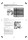
Caution:
Total amount of current from the respective connectors for DC OUT, REMOTE, VF,
and LENS should not exceed 2.5 A.