


13
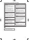
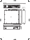
Parts and their functions
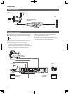
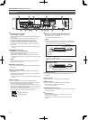
Front panel
1
POWER switch
This is the unit’s power switch.
Move it to the ON position to turn on the power.
2
POWER lamp
This lights when power switch
1
is set to ON and power is supplied
to the unit.
3
ALARM lamp
[OPEN]
This lights when the unit and camera are not connected by the optical
fiber multi cable.
[SHORT]
This lights when the cable connecting the unit and camera has been
short-circuited.
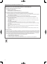
4
TALLY/CALL button
This functions both as the CALL button, which is pressed when
calling the camera side, and the tally lamp.
The lamp remains lit while tally signals (R) are input.
When the CALL button is pressed on the camera, ROP or CCU, it is
lit while no tally signals are input, and off while tally signals are input.
5
SYS PRIV switch
This switch is for selecting the party to call using the intercom.
SYS : For calling the intercom on the system side and camera side.
PRIV : For making private calls between the unit and camera side.
6
MIC switch
ON : The intercom microphone is turned on.
OFF : The intercom microphone is turned off.
PTT : The intercom microphone is on only while the switch is held
down.
7
PGM switch
ON : The sound of PGM is mixed with the intercom sound.
OFF : The sound of PGM is not mixed with the intercom sound.
8
LEVEL controls
[INCOM]
These controls are for adjusting the volume level of the sound heard
through the intercom.
[PGM]
This is for adjusting the volume level of the PGM sound to be mixed
with the intercom sound.
9
INCOM connector
This connector enables calls with the intercom line of the camera.
Calls cannot be made with the camera when the camera’s power is
OFF.
:
MENU button
When you hold down this button, the menu screen is displayed on the
picture monitor and the MENU button lights.
Holding down this button while a menu is displayed ends menu
display and turns off the MENU button.
When the REMOTE OPERATION menu is displayed by ROP
operation, the menu display of this unit ends and also the MENU
button turns off.
Refer to “Menu operations” of <Operations and Settings> (page 9).
SELECT dial
This jog dial is for menu screen operations.
When the SELECT dial is turned clockwise, the cursor moves down;
conversely, when it is turned counterclockwise, the cursor moves up.
Press the SELECT dial to select the menu items.
<
Memory card access lamp
This is lit while the memory card is being accessed.
=
Memory card slot
Insert a memory card (sold separately).
A memory card can be used to set this unit and upgrade the software.
Refer to “SD CARD Screen” of <Operations and Settings> (page
25).