


14
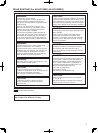
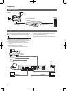
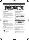
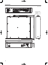
Rear panel
>
HD/SD SDI OUT connectors
[1], [2], [3/PM], and [4/PM]
These connectors (BNC) are for outputting SDI signals in HDTV and
SDTV formats.
The HD/SD output mode can be selected by setting a menu item.
The output mode can be switched between the [1] and [2]
combination and between the [3/PM] and [4/PM] combination.
SDI output from [3/PM] and [4/PM] can be switched to main line
image output or picture monitor output by setting a menu item or by
ROP control.
Refer to “SETTING1 Screen” of <Operations and Settings> (pages
11 and 27).
?
RETURN IN connectors
[HD/SD SDI 1] and [HD/SD SDI 2]
These connectors (BNC) are for inputting SDI signals for return
images in HDTV and SDTV formats.
The HD/SD input mode can be selected by setting a menu item.
Refer to “SETTING1 Screen” of <Operations and Settings> (pages
11 and 27).
[VBS]
This connector (BNC) is for inputting analog composite signals for
return images in SDTV format.
PROMPT connector [IN]
This connector (BNC) is for inputting SD analog composite signals for
the prompter.
A
VBS connector [OUT/PM]
This connector (BNC) is for outputting analog composite signals in
SDTV format.
Output can be switched to main line image output or picture monitor
output by setting a menu item.
Refer to “SETTING1 Screen” of <Operations and Settings> (pages
11 and 27).
B
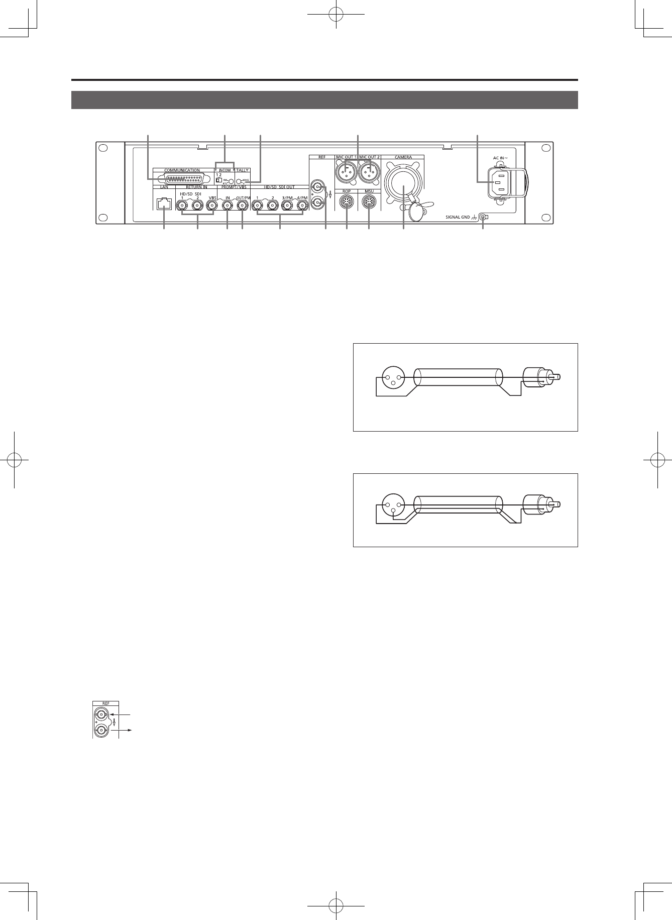
REF connectors
These connectors (BNC) are for inputting reference signals.
Black burst (BB) signals and tri-level sync signals can be input, and
the type of signals input is recognized automatically.
When no cable is connected to the loop-through output connector,
the connector is automatically terminated at 75 Ω. Connecting a cable
to this connector releases 75 Ω termination.
When a cable is connected to the loop-through output connector, be
sure to connect the other end of the cable to a connector.
Reference signal input
Loop-through output
MIC OUT 1 connector and MIC OUT 2 connector
These connectors are for outputting the analog signals of
microphones 1 and 2 of the camera.
The microphone level is 0 dBm/600 Ω.
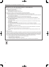
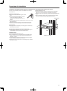
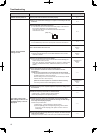
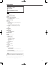
<Notes>
When connecting the MIC OUT 1 and MIC OUT 2 connectors (XLR
terminals) to the unbalanced input terminals of an external device,
connect them as shown in the diagram below.
1
3
2
XLR terminal
PIN terminal
(unbalanced input terminal)
1: Ground (shield)
2: Hot (+Ve)
3: Cold (–Ve)
Make pin 3 open.
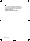
Some commercially available adapter connectors and adapter
cables have pin 3 shorted to pin 1.
Using such an adapter connector or adapter cable will cause a
failure.
1
3
2
DO NOT USE
Do not use an adapter connector or adapter cable
that has pin 3 shorted to pin 1.
CAMERA connector
This connector is for connecting the optical fiber multi cable (sold
separately).
E
ROP connector
This connector is for connecting a ROP (sold separately).
MSU connector
This connector is for connecting an MSU (sold separately).
This connector is for future function expansion.
It is not currently supported.
COMMUNICATION connector
This connector is for connecting the intercom signals and tally signals
to the external system.
H
LAN connector
This LAN connector (RJ45) is for connecting a computer when
configuring the Web settings.
Use a 10Base-T or 100Base-TX crossover cable to connect the
computer.
Parts and their functions (Continued)