


15
I
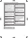
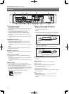
INCOM switches
[1/ 2]
This switch allows you to switch the intercom to be input to the
COMMUNICATION connector
between 1 and 2 to enable calls
with the selected camera.
Initial value: [1]
[4W/RTS]
This switch allows you to switch the system of the intercom signal to
be input to the COMMUNICATION connector
between 4-wire (4W)
and RTS.
Initial value: [4W]
When using the unit and camera combined on a one-to-one basis
instead of using the intercom equipment on the system side, set
this switch to the 4W position.
If you set this switch to the RTS position, be sure to connect an
RTS system.
When using the unit with an RTS system, terminate pins 1 and 3 of
the COMMUNICATION connector
using a terminating resistor
(200 Ω). (In the case of intercom signal 2, terminate pins 14 and
16.)
Refer to “Connector pin assignment table” of <Operations and
Settings> (page 38).
TALLY switch
[MAKE/V]
This switches the interface for the tally signal to be input to the
COMMUNICATION connector
between contact type (MAKE) and
voltage type (V).
Initial value: [MAKE]
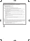
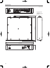
K
AC power socket [AC IN
]
This socket is for inputting AC power.
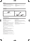
Connect the supplied power cable, and use a 3-prong outlet and
ground the unit properly.
Grounding terminal [SIGNAL GND]
Connect this to the system ground.
Parts and their functions (Continued)