


Cable Compensator AW-RC400
36 (E)
ENGLISH
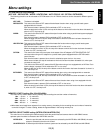
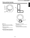
Parts and their function
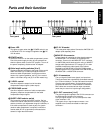
1Power LED
This lights up green when the (2) POWER switch is set
to ON while a DC 12V voltage is supplied to the (7) DC
12V IN socket.
2POWER switch
Set this to ON to turn on the cable compensator’s power.
Part of the power supply circuitry will still operate even
when the power switch is at the OFF position. To turn off
the power completely, disconnect the AC adaptor.
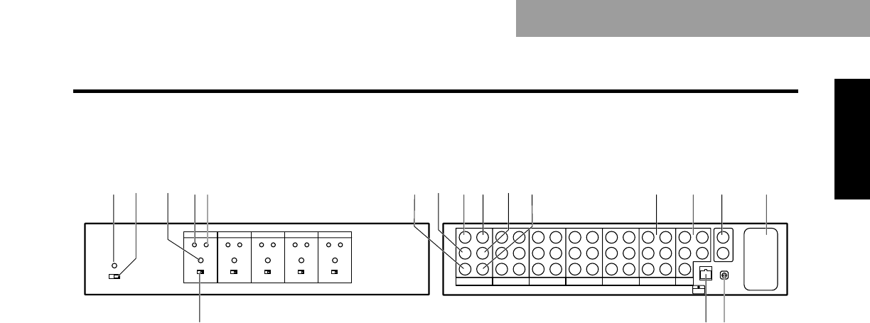
3Cable length setting switches [0 to 5]
Set these switches according to the length of the coaxial
cable connected. [0] is used to provide the minimum
amount of cable compensation, and [5] the maximum
amount. As a general guideline, set to [1] if the coaxial
cable is 100 meters long, and [2] if it is 200 meters long.
4Y LEVEL control
Use this to adjust the output level of the cable
compensation output signals (video output).
5F RESPONSE control
Use this to adjust the amount of cable compensation
(frequency response compensation) for the cable
compensation output signals.
6SHORT/LONG selector switch
This is normally used at the SHORT position. Set it to
LONG if the coaxial cable from the camera is a long one
and the camera’s sync adjustment range is insufficient, or
if the cable compensator is used as part of a system
(another cable compensator is required) in which the
coaxial cable (5C-2V or equivalent) connected to the
camera is longer than 500 meters.
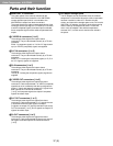
7DC 12V IN socket
This is the power input socket. Connect the AW-PS301 AC
adaptor (sold separately) here.
8MONI SEL IN connector
Control signals for selecting the video signals output to
the MONITOR1 or 2 connector are supplied to this
connector. Connect it to the MONI SEL OUT connector
on AW-RP400 pan/tilt head controller using a 10BASE-T
straight cable (equivalent to UTP category 5). It is then
possible to output the video signals of the camera
selected by the AW-RP400 or the AW-CB400 remote
operation panel which is connected to the AW-RP400, to
the MONITOR1 or MONITOR2 connector.
9G/L IN connectors
The sync signals (black burst signals) are input here.
These connectors are automatically terminated internally
by a 75-ohm resistance. The top and bottom connectors
have the same specifications, and the signals can be
connected to either one. The termination is released if
BNC cables are connected to both input connectors
(when they are used in a loop-through configuration).
:G/L OUT connectors [1 to 5]
The genlock signals supplied to the G/L IN connector can
be distributed and output to five cameras.
Use sync signal outputs 1 to 5 to correspond to video
signal channels 1 to 5.
The signals of sync signal output connector 1 are
supplied to the camera connected to video input
connector 1.
12345
687
>=<?@A ; : 9 B
Front panel Rear panel