8 C1302M-F (11/08)
DIP SWITCH SETTINGS
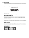
Configure the receiver address, termination, and baud setting for the system. The DIP switches to configure these settings are located on the top
of the power module.
NOTE: No DIP switch settings are required for Coaxitron control.
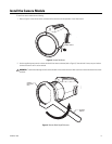
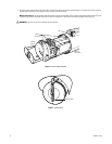
Figure 3 shows the default settings for the DIP switches. Refer to the following to configure the ExSite system settings.
Figure 3. Default DIP Switch Settings
PROTOCOL SETTINGS
The ExSite system automatically detects the type of protocol. No switch settings are required to set Coaxitron or RS-422 P and D protocols.
RECEIVER ADDRESS SETTINGS (SW1)
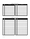
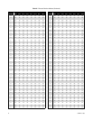
The default address is 2 for P protocol. Refer to Table A for address settings that use P protocol. Maximum number of receivers is 32.
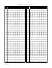
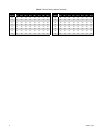
The default address is 1 for D protocol. Refer to Table B for address settings that use D protocol. Maximum number of receivers is 254.
TERMINATION SETTING (SW2)
When connecting more than one ExSite system to a single controller, terminate the unit farthest from the controller. Termination is required only
for the last unit in the series. The unit is shipped from the factory in the unterminated OFF position. To terminate the unit, set the SW2 switch to
the ON position.
BAUD SETTINGS (SW3)
Pelco’s D-type controllers are set for 2400 baud. The default setting for the unit is 2400 baud. If you are using a Pelco D-type controller, do not
reset the SW3 switches.
P-type controllers can operate at 2400, 4800, and 9600 baud. Set the SW3 switches (6, 7, and 8), located on the top of the power module, to the
same baud as the P-type controller.
Switch Settings for SW3
Switch Number SW3-6 SW3-7 SW3-8
2400 Baud Off Off Off
4800 Baud On Off Off
9600 Baud Off On Off
SW1
SW2
SW3
1
2
3
4
5
6
7
8
1
2
3
45
6
7
8
1
on
on
ON
SW1-1 is set to the ON position.
All other switches are set to the OFF position.


