


8 Pelco Manual C546M (8/98)
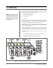
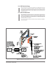
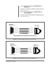
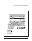
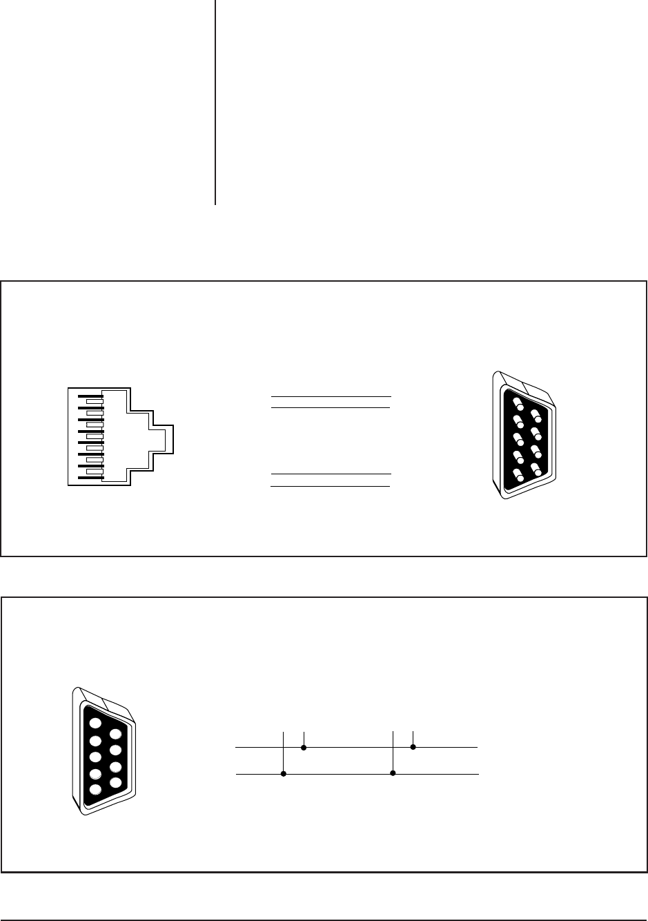
Figure 4. Pin Connections Between a CM9760-PEX and CM9760-CC1
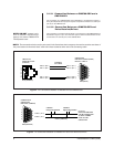
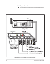
Figure 5. Pin Connections Between a CM9760-PEX and Pelco Receiver/Drivers
3.1.3.1 Connection Between a CM9760-PEX and a
CM9760-CC1
The connection of a CM9760-PEX and a CM9760-CC1 is illustrated in Figure 4.
Every Port Expander card input port requires a separate connection to a comm port
(RJ-45) on the CM9760-CC1.
3.1.3.2 Connection Between a CM9760-PEX and
Pelco Receiver/Drivers
The connection of a camera receiver/driver to a comms port on the CM9760-PEX is
illustrated in Figure 5. Up to 16 of the same type of camera receiver/drivers can be
connected to one comms port on the CM9760-PEX.
NOTE:
DO NOT
connect a mix-
ture of different receiver/driver
types to the same CM9760-PEX
Port Expander card.
PIN 5 = (Tx +)
PIN 9 = (Tx –)
CAMERA
RECEIVER/DRIVER
– +
CAMERA
RECEIVER/DRIVER
– +
RS422 (SIMPLEX)
UP TO 16
RECEIVER/DRIVERS
CAN BE CONNECTED
TO EACH COMMS
PORT ON THE
CM9760-PEX
DB9 (FEMALE)
6
7
8
9
1
2
3
4
5
COMMS PORT
CM9760-PEX
DB9 PORT (FEMALE)
1
2
3
4
5
6
7
8
CM9760-CC1
SERCOM 8 PORT
(FEMALE)
RJ45 (FEMALE)
PIN 1 = (Tx +)
PIN 2 = (Tx –)
PIN 8 = (Rx +)
PIN 7 = (Rx –)
PIN 5 = (Tx +)
PIN 9 = (Tx –)
PIN 4 = (Rx +)
PIN 8 = (Rx –)
CONNECT
VIA CABLE
DB9 (MALE)
5
4
3
2
1
9
8
7
6
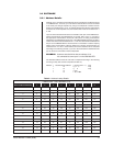
CM9760-PEX
DB9 INPUT PORTS (MALE)
INPUTS 1 THRU 5
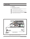
NOTE:
The connection devices and/or ports used in the illustrations that accompany the next few sections are those of
the ports located on the device itself, rather than those located at either end of the connecting cable.